Hardware Descriptions
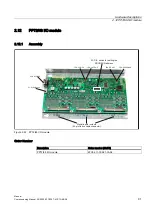
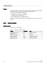
2.12 PP72/48 I/O module
Manual
Commissioning Manual, 05/2008, 6FC5397–4CP10–4BA0
97
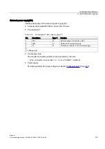
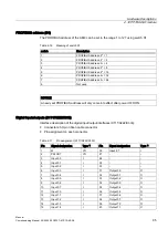
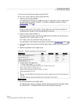
(1) If you are using the internal power supply P24OUT
(2) If you are using an external power supply P24OUT
ext
●
Internal supply voltage (P24OUT)
The internal power supply for the digital inputs (X111, X222, X333: Pin 2) is derived from
the general power supply of module X1, pin 2 (P24). Specification: Refer to Section
CAUTION
A max. current of Iout = 0.5 A on X111, X222, X333: Pin 2 must not be exceeded. An
exceeding of the maximum current might destroy the module.
●
External supply voltage (P24OUT
ext
)
If an external power supply is used for the digital inputs, their reference ground must be
connected to X111, X222, X333: Pin 1 (M)
X111, X222, X333: Pin 2 (P24OUT) then remains open.
For specification of the external power supply, see Subsection "Power supply" (Page 100).
●
Connection cable: The required connecting cables (ribbon cables) must be provided by
the user
.
●
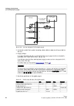
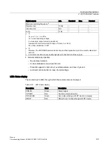
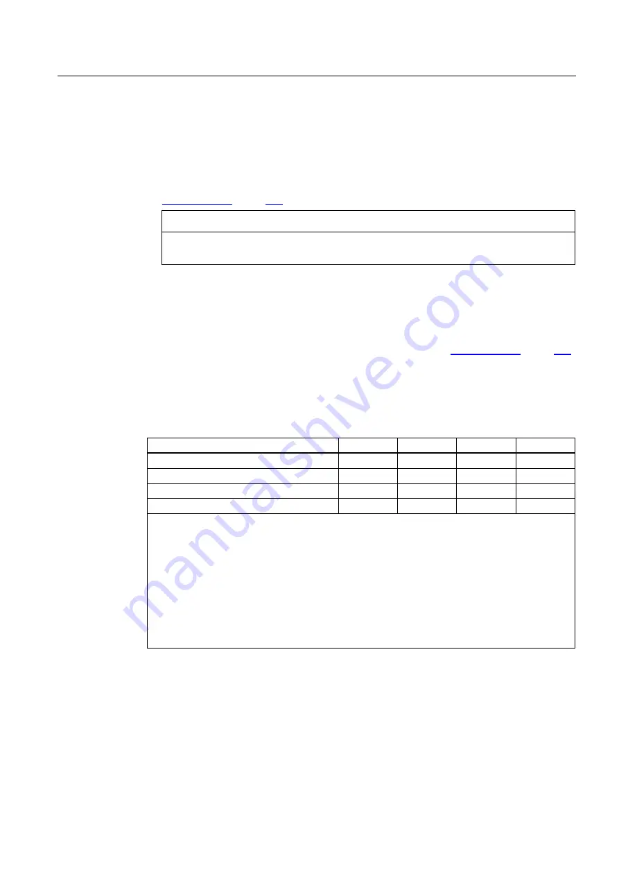
Electrical specification of the digital inputs:
Table 2-18 Electrical specification of the digital inputs:
Digital inputs
min.
Standard
Max.
Nominal
Voltage at high signal level (U
H)
15 V
1)
30 V
24 V
Input current I
IN
at V
H
2 mA
-
15 mA
-
Voltage at low signal level (U
L)
-30 V
-
+5 V
0 V
Signal delay time T
PHL 2)
0.5 ms
-
3 ms
-
•
Supply voltage of the digital inputs
1) Typical output voltage: V
CC
- I
OUT
<R
ON
V
CC
current operating voltage (P24OUT) to X111, X222, X333: Pin 2
Max. output current I
OUT
: 500 mA per pin
Max. short-circuit current: 4A (max. 100ms, V
CC
= 24V)
Internal resistance R
ON
: 0.4 W
•
2)
Moreover, the PROFIBUS communication time and the application cycle time must be taken into
account.
•
Incorrect connection causes neither high level nor destruction of the inputs.
Digital outputs:
●
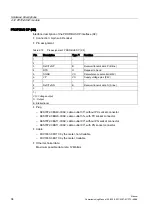
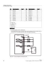
Terminal assignment for the digital outputs
The following figure shows an example of the terminal assignment for the digital outputs
on connector X111. Connectors X222 and X333 are assigned analogously.

