
Drive commissioning (SINAMICS)
9.2 ONLINE commissioning
Manual
322
Commissioning Manual, 05/2008, 6FC5397–4CP10–4BA0
9.2.7
Drive unit: Check configuration
After configuring all of the drives, we recommend checking the DRIVE-CliQ interconnection
recognized by the STARTER during automatic configuration with the drive unit
interconnection.
Implementation
Perform the following actions for each drive unit:
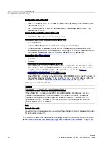
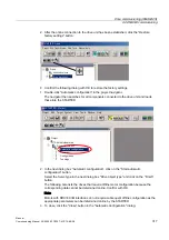
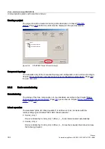
1.
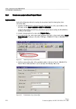
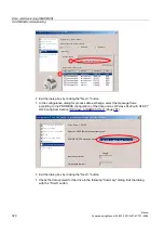
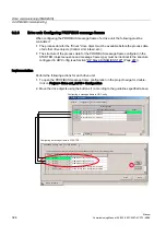
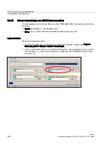
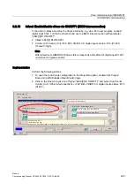
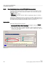
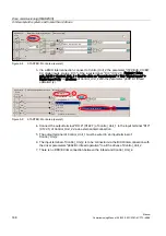
Open the topology tree via Project navigator > Any drive > Drive navigator (double-click)
> Dialog > Device configuration" > "Check topology" button.
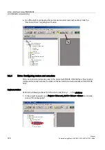
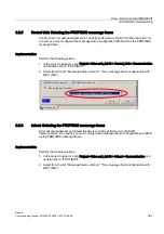
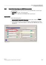
:KDWGR\RXZDQWWRGR"
&KHFNWRSRORJ\
&RQILJXUH
WKHGULYH
'HYLFHFRQILJXUDWLRQ
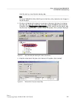
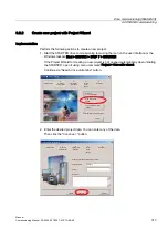
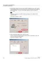
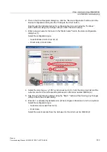
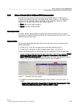
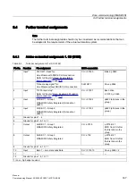
2.
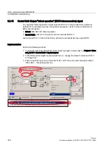
Compare the DRIVE-CliQ topology displayed in the STARTER with the topology of the
drive unit.
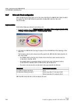
The following rules must be observed with regard to the DRIVE-CliQ interconnection of
the components:
–
The DRIVE-CLiQ cable from the Control Unit to the first power module must be
connected to interface X200.
–
The DRIVE-CLiQ connections between each of the power modules should be
connected from interface X201 to X200 on the next component.
–
The motor encoder must be connected to the associated Motor Module:
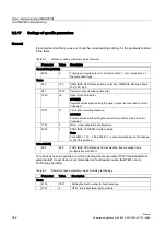
Component
Motor encoder connection
Single Motor Module (booksize)
X202
Double Motor Module (booksize)
Motor connection X1: Encoder at X202
Motor connection X2: encoder to X203
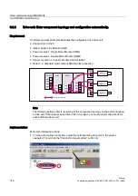
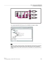
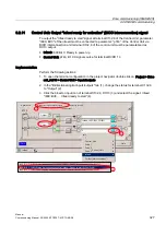
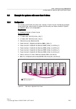
DRIVE-CliQ interconnection of the example structure: