
Ethernet communication
7.7 HT 2
Manual
226
Commissioning Manual, 05/2008, 6FC5397–4CP10–4BA0
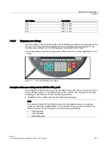
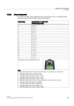
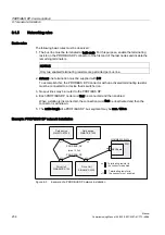
7.7.2.3
Write display-line
The writing of a display line covers the following points:
1.
Selection of the display lines to be written in the output area: AB m + 1, Bit 1 and Bit 0
2.
Writing the data in the output area: AB m + 4 to AB m + 19
3.
Setting the write request in the output area: AB m + 1, Bit 7
4.
Waiting for the acknowledgement of the write request in the input area: EB n + 5, Bit 7
5.
Resetting the write request in the output area: AB m + 1, Bit 7
The user (machine manufacturer) must write a display line in the PLC user program.
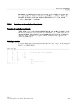
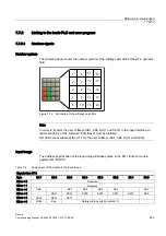
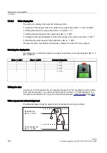
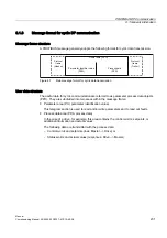
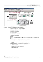
Selecting the display-line
The display line in which the data is to be output is selected via the output signals: AB m + 1,
Bit 1 and Bit 0.
AB m + 1, Bit 1
AB m + 1, Bit 0
Selected display-line
0
0
1. Line
0
1
2. Line
1
0
3. Line
1
1
4. Line
/LQH
/LQH
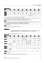
Writing the data
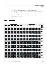
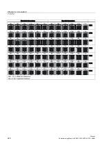
A maximum of 16 characters can be output per display line. The characters must be written
in the output area AB m + 4 (outermost right character) to AB m + 19 (left character). The
character set available in HT 2 is given in the following chapter: Character Map (Page 227)
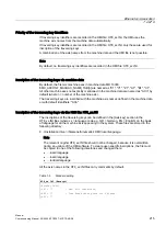
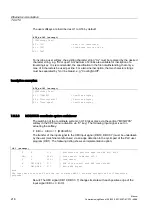
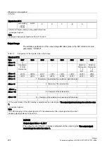
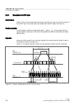
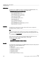
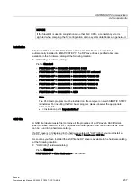
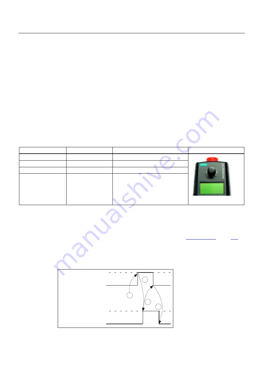
Write request and acknowledgement
The following figure shows the signal chart of a display-line during the writing:
D
E
G
F
5HTXLUHPHQW
$%P%LW
$FNQRZOHGJPHQW
(%P%LW