Electrical installation
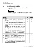
4.2 Checklist for electrical installation
Converter cabinet units
Operating Instructions, 07/2016, A5E03347396A
63
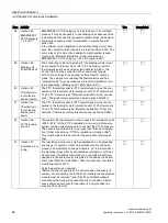
Item Activity
Yes
Completed
7 The cable shields must be properly applied and the cabinet properly grounded at the
points designated for that purpose (see "Electrical installation/EMC-compliant instal-
lation").
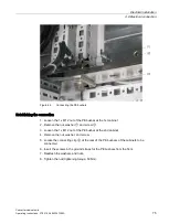
8 The voltages of the fan transformers (-T1-T10/-T20) must be adapted to the supply
voltage for the cabinet unit. The voltage must be adapted in both transport units
(see section "Electrical installation / Power connections / Adjusting the fan voltage
(-T1-T10/-T20)").
9 A yellow warning label is attached to the basic interference suppression module at
each connection clip.
•
The warning label must removed from the connection clip (by pulling it off) if the
connection clip is to remain in the unit (operation on a grounded line supply).
•
The warning label must be removed together with the connection clip if the unit
is operated on a non-grounded line supply (IT system).
(See "Electrical installation/Power connections/Removing the connection clip to the
basic interference suppression module for operation on a non-grounded line supply
(IT system)").
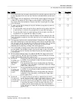
10 The type plate can be used to ascertain the date of manufacture. If the period from
the date of manufacture to initial commissioning or the cabinet unit downtime is less
than two years, the DC-link capacitors do not have to be formed. If the unit has been
non-operational for longer than two years, forming must be carried out (see
"Maintenance and Servicing / forming of DC-Link Capacitors").
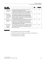
11 The circuit breaker's tripping current must be set in accordance with the specific
plant conditions. The feedback contact of the circuit breaker is wired to the terminal
block –X50 (see Section "Electrical Installation/Power connections/Adapting the
circuit breaker").
12 With an external auxiliary supply, the cable for the 230 VAC supply must be con-
nected to terminal –X40 (see "Electrical installation / Power connections / External
supply of the auxiliary supply from a secure line").
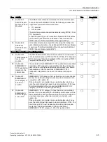
13 Option L07
dv/dt filter com-
pact plus Vol-
tage Peak
Limiter
During commissioning, the filter must be selected via STARTER
or AOP30. You are advised to check the selection by ensuring
that p0230 is set to 2.
The required parameters are set automatically (see "Electrical
installation / Other connections / dv/dt filter compact plus Voltage
Peak Limiter (option L07)").
14 Option L10
dv/dt filter plus
Voltage Peak
Limiter
During commissioning, the filter must be selected via STARTER
or AOP30. You are advised to check the selection by ensuring
that p0230 is set to 2.
The required parameters are set automatically (see "Electrical
installation / Other connections / dv/dt filter plus Voltage Peak
Limiter (option L10)").
15 Option L19
Connection for
external auxilia-
ry equipment
To supply auxiliary equipment (e.g. separately-driven fan for
motor), the drive must be properly connected to terminals -X155:1
(L1) to -X155:3 (L3). The supply voltage of the auxiliary equip-
ment must match the input voltage of the cabinet unit. The load
current must not exceed 10 A and must be set at -Q155 in ac-
cordance with the load connected (see "Electrical installation /
Other connections / Connection for external auxiliary equipment
(option L19)").
Set value:
__________
Summary of Contents for SINAMICS G150
Page 1: ......
Page 2: ......
Page 8: ...Foreword Converter cabinet units 8 Operating Instructions 07 2016 A5E03347396A ...
Page 18: ...Table of contents Converter cabinet units 18 Operating Instructions 07 2016 A5E03347396A ...
Page 679: ......
Page 680: ......


