Electrical installation
4.10 Other connections
Converter cabinet units
Operating Instructions, 07/2016, A5E03347396A
125
4.10.4
Overvoltage limitation (option L21)
Description
The option includes the installation of surge arresters and upstream fuses for each line
phase. The signaling contacts of the surge arresters are connected in series for monitoring
purposes and routed to a customer interface.
Safety instruction
Note
Remove the connection clip for the interference-suppression capacitor for operation on an IT
supply
For operation on an IT supply, the connection clip for the interference suppression capacitor
must be removed (see "Electrical installation / removing the connection clip for the
interference suppression capacitor for operation on a non-grounded supply system (IT
supply)").
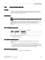
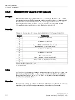
X700 - monitoring the surge arresters
Table 4- 27 Terminal block X700 Monitoring the surge arresters
Terminal
Designation
1)
Technical data
1
NC
Max. load current:
- at 24 V DC: 1 A
- at 230 VAC: 0.5 A
4
NC
Max. connectable cross-section: 2.5 mm²
1)
NC: normally-closed contact
Reason why the monitoring responded
After the monitoring function responds at terminal block X700:1/4, the cause must be
identified:
●
Surge arresters (-A703, -A704-, A705) have a display showing the operating state.
●
The upstream fuses (-Q700) are monitored using phase failure monitoring (-B700), which
has an LED status display. In the event of a fault as a result of a defective fuse, the fuses
(-Q700) must be checked, and if required, replaced after removing the fault.
Replacement of the surge arresters
In the event of a fault, the surge arresters must be replaced.
Summary of Contents for SINAMICS G150
Page 1: ......
Page 2: ......
Page 8: ...Foreword Converter cabinet units 8 Operating Instructions 07 2016 A5E03347396A ...
Page 18: ...Table of contents Converter cabinet units 18 Operating Instructions 07 2016 A5E03347396A ...
Page 679: ......
Page 680: ......

