Electrical installation
4.10 Other connections
Converter cabinet units
Operating Instructions, 07/2016, A5E03347396A
149
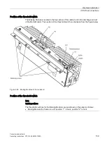
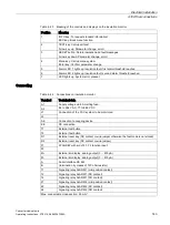
Figure 4-32 Removing the CBE20 from the option slot on the Control Unit
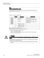
X1400 Ethernet interface
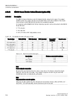
Table 4- 47 Connector X1400, port 1 - 4
Pin
Signal name
Technical data
1
RX+
Receive data +
2
RX-
Receive data -
3
TX+
Transmit data +
4
Reserved, do not use
5
Reserved, do not use
6
TX-
Transmit data -
7
Reserved, do not use
8
Reserved, do not use
Screened
backshell
M_EXT
Screen, permanently connected
Connector type: RJ45 socket
Summary of Contents for SINAMICS G150
Page 1: ......
Page 2: ......
Page 8: ...Foreword Converter cabinet units 8 Operating Instructions 07 2016 A5E03347396A ...
Page 18: ...Table of contents Converter cabinet units 18 Operating Instructions 07 2016 A5E03347396A ...
Page 679: ......
Page 680: ......

