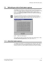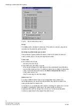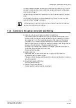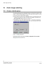
Alarm image switching
81
Siemens Building Technologies
Fire Safety & Security Products
06.2008
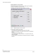
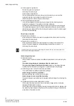
Alarm picture on monitor
z
Alarm picture on monitor x
if the length has been set to 1, the ‘shuttle alarm’ and ‘alarms in a row’ settings
for the
Alarm image
options are inactive (grey).
If the length has been set to greater than 1, they are active (black).
(Set using the arrow keys)
z
Alarm pictures on monitor x:
This setting determined the length of the alarm monitor string. A box is used to
display the monitor string (see section 12.2). A monitor string can contain no
more than 8 monitors.
(Set using the arrow keys)
z
Pictures per alarm:
Each alarm event leads to the display of a single, or a maximum of four
simultaneous images. The alarm images correspond to the camera group: i.e. if
one image is displayed per alarm event, only the image from the first camera in
the group where the alarm has triggered will be switched If two images are
required per alarm event, the images from cameras 1 and 2 in the relevant
group will be displayed, etc. As a group can include no more than four cameras
(see section 11.2), the maximum number of images per alarm event is also four.
(Set using the arrow keys)
Alarm zone
You can set the alarm zones here by selecting any of the zones (8 maximum)
whose alarm events are to be switched to the monitor in question.
For example:
Only alarm zone 1 is active:
Only alarms generated by the alarm lines allocated to alarm zone 1 will be
displayed (see section 11.1)
It is of course possible to program a monitor to display alarms from a number of
different alarm zones. The alarm zone status in terms of time-enabling is also
displayed here (e.g.
always
, ‘07:00<-> 12:00’). See section 10.4 for more details.
Control response to alarms
z
Setting the control output
No control output in response to an active alarm
(Set using the arrow keys)
In case of alarm (logical Or) set control output x:
If a video recorder is used to record images, enter the number of the control
output (1 -8) to which the recorder is connected here.
Control output 1 corresponds to control lead D0 on COM2 on the
SIMATRIX SYS or the ‘ALARM OUT’ output on the SIMATRIX 648/164, etc.
(Enter the number of the control output using the arrow keys)

