Basic alarm parameters
71
Siemens Building Technologies
Fire Safety & Security Products
06.2008
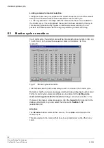
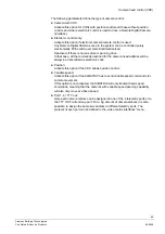
Fig. 53
Basic alarm parameters for SIMATRIX SYS
10.1 Alarm
configuration
Alarm line connection to S-I/O
.(only in the case of SIMATRIX SYS)
Indicate here to which alarm input you have connected your first alarm line. Serial-
I/O 0 will normally be left free, while S-I/O 1 to S-I/O 4 are normally reserved for
keyboards. This means that the first alarm line will generally be connected to S-I/O
5. You can of course connect your alarm lines to S-I/O 1 and further, if these I/Os
are not used for keyboards. In principle, you can allocate the first input in any way
you want. The following allocation of the alarm inputs to the alarm input modules
applies:
Important for SIMATRIX SYS:
Setting parameters for the
UART-MX 16 interface card:
S-I/O 0 to S-I/O 15 correspond to I/O-terminal strip 0-15
(UART-MX 16-0/ no.1 to UART-MX 16-0/ no.16)
The AS32MX and A32MX alarm cards each have 32 alarm inputs
Setting parameters for the
AS32MX
alarm card:
S-I/O 16 to S-I/O 47 correspond to AS32MX-1/ no.1 to AS32MX-1/ no.32
S-I/O 48 to S-I/O 79 correspond to AS32MX-2/ no.1 to AS32MX-2/ no.32
Setting parameters for the
A32MX
alarm card:
S-I/O 32 to S-I/O 63 correspond to A32MX-1/ no.1 to A32MX-1/ no.32
S-I/O 64 to S-I/O 95 correspond to A32MX-2/ no.1 to A32MX-2/ no.32
z
xx alarm lines active:
Use the arrow keys to indicate the number of connected alarm lines here.
z
External alarm from group xx:
External alarms are generated by external computers (e.g. GMA Topsis) and are
transmitted to the SIMATRIX via a communications interface (COM 3, COM 4).
It is only necessary to set from which alarm line onwards allocation should take
place if this type of configuration is used (use the arrow keys to do so).

