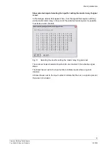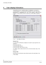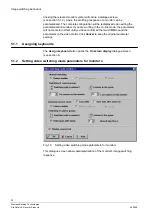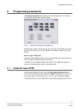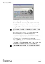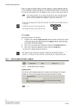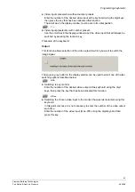
Image switching behaviour
29
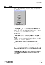
Siemens Building Technologies
Fire Safety & Security Products
06.2008
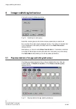
This dialogue screen presents a graphical representation of the switching
behaviour of the video outputs.
Alarm switching behaviour is presented in the
Alarm switching behaviour display
dialogue screen.
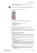
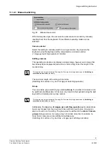
Each SIMATRIX output appears as a monitor icon.
For example:
Fig. 18
Representation of the switching response of a video output
1
Keyboard no. 4
2
Video switching mode: automatic picture cycle at switch-on
(
Auto-start after power on
option)
3
Monitor number
4
switchable cameras: 1 to 48
C: 1 ...48
indicates which cameras have been released for switching on this
monitor (in this example: cameras 1 to 48).
When a monitor has been assigned to a keyboard for displaying user entered data,
a representation of the keyboard and its number will appear above the monitor icon
(here: no. 4).
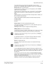
Display options for video switching modes
z
Automatic picture cycle enabled
If an automatic picture cycle has been enabled, a circular sequence icon with
two arrowheads and a camera icon will appear in the corresponding monitor
icon.
z
An
A
in the camera icon indicates that the
Auto-start after power on
option is
active (see section 5.1.2.2).
z
Monitor string
If a number of monitors have been grouped in a monitor string, this is shown by
a box around the monitors involved.
A
box with black lines
indicates a monitor string for manual switching. In this
case, the first monitor in the string (the master monitor) is darker than the rest.
A
box with yellow lines
indicates a monitor string for automatic switching.
In this case, the first monitor in the string (the master monitor) is
darker
than the
rest.
z
Alarm monitors
Monitors displayed in
red
are alarm monitors, which can be parameterised in the
Programming of the alarm switching mode on output x
dialogue box
(see section 12.2.2).


