Procedure
1. Select the "Graphics Designer" entry in the navigation window.
The detail view shows all the pictures belonging to the project. The pictures displayed also
include the default pictures and template pictures provided by PCS 7 SMART.
Default pictures and template pictures are designated with the "@" character before the
name.
2. Double-click the "RMT1.pdl" picture in the detail view.
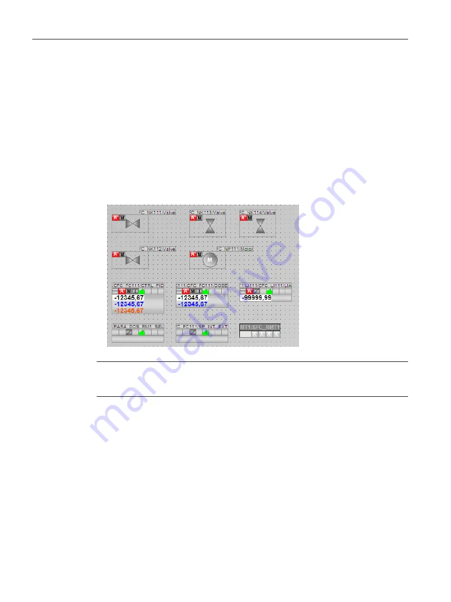
The process picture opens in Graphics Designer. The view shows that this process picture
already contains objects although you have not yet inserted any. These are the block icons
that you created in the process picture with the "Create block icons" function in SIMATIC
Manager. You can also see that the block icon for the valve has been inserted both in the
horizontal alignment and vertical alignment variants. These two variants are influenced by
the setting in the process object view in the "Picture Objects" tab that you made when
assigning parameters for the CFCs.
Note
In the example, the automatically inserted block icons (for example, for the "CTRL_PID"
controller) were moved.
9.6.3
Opening various toolbars
Introduction
The most important toolbars and dialog boxes are open by default. If you inadvertently close
toolbars or dialog boxes, you should know how to make them visible again.
Prerequisites
The process picture is open in the Graphics Designer.
Configuring the operator station
9.6 Working in general with the Graphics Designer
PCS 7 SMART Getting Started - Part 1 (V9.0 with APL)
154
Getting Started, 12/2017, A5E42181435-AA


