Operating Instructions
Samsung Electronics
3-27
USB interface (VP-L907 only)
ENGLISH
61
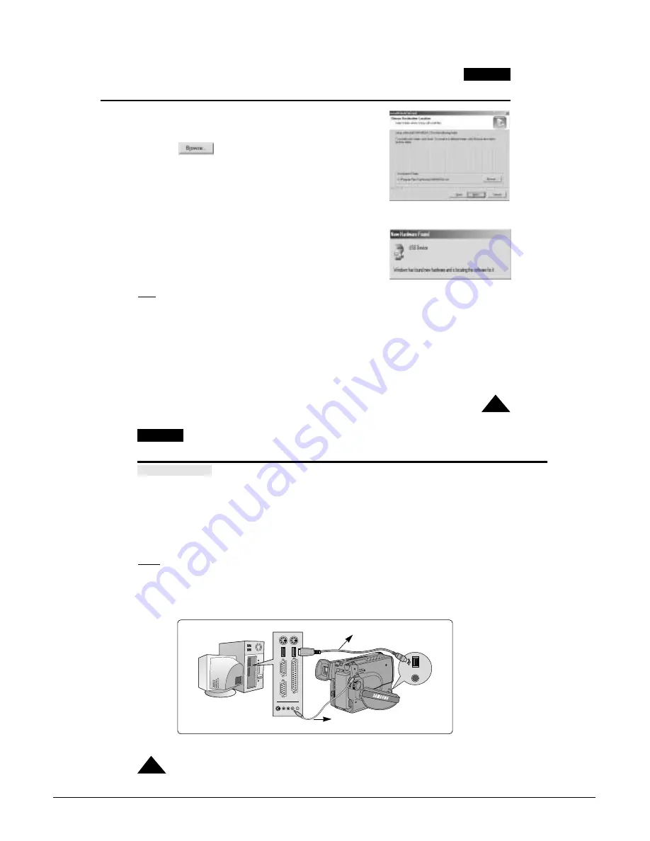
4. The window below displays the folder to install the program.
■
The program is installed in the following folder.
C:\Programfiles\Samsung\USB Media 2.0
■
Click to change the folder.
5. Connect the camcorder to PC.
6. PC finds the new hardware and installs the driver automatically.
7. If the driver is installed, the installation is completed.
8. Execute USB Media 2.0 player on the Windows wall paper.
Note:
■
USB Media 2.0 User's Manual is included on the accompanying CD in Adobe's Portable Document Format (PDF).
The user's manual can be viewed using Acrobat Reader software, which is also included on the CD.
(The Acrobat Reader is a freeware product of Adobe Systems, Inc.)
4.
6.
ENGLISH
62
Connecting to a PC
1. Connect a USB cable to the USB port on the PC.
2. Connect the other end of the USB cable into the proper terminal on the camcorder. (USB jack)
3. Connect the audio cable to the Line input jack of the PC.
If the PC has no Line input jack, connect the audio cable to the MIC input jack.
This connection, however, may produce noise depending on the PC.
Notes:
■
If you disconnect the USB cable from the PC or the camcorder while transferring, the data transmission will stop
and the data may be damaged.
■
If you connect the USB cable to a PC via a USB HUB or simultaneously connect the USB cable along with other
USB devices, the camcorder may not work properly.
-
If this occurs, remove the other USB devices from the PC and reconnect the camcorder.
USB interface (VP-L907 only)
MIC
USB Cable
USB AUDIO Cable
Summary of Contents for VP-L900
Page 5: ...Product Specification 2 2 MEMO ...
Page 51: ...4 18 Disassembly and Reassembly Samsung Electronics MEMO ...
Page 79: ...5 28 Alignment and Adjustments Samsung Electronics MEMO ...
Page 109: ...Circuit Operating Description 6 30 Samsung Electronics MEMO ...
Page 124: ...Deck Operating Description Samsung Electronics 7 15 Fig 7 14 ...
Page 126: ...Deck Operating Description Samsung Electronics 7 17 Fig 7 16 ...
Page 128: ...Deck Operating Description Samsung Electronics 7 19 Fig 7 17 ...
Page 130: ...Deck Operating Description Samsung Electronics 7 21 Fig 7 18 ...
Page 132: ...Deck Operating Description Samsung Electronics 7 23 Fig 7 19 ...
Page 134: ...Deck Operating Description Samsung Electronics 7 25 Fig 7 20 ...
Page 136: ...Deck Operating Description Samsung Electronics 7 27 Fig 7 21 ...
Page 138: ...Deck Operating Description Samsung Electronics 7 29 Fig 7 22 ...
Page 139: ...Deck Operating Description 7 30 Samsung Electronics MEMO ...
Page 142: ...Samsung Electronics 10 1 10 Wiring Diagram ...
Page 143: ...Wiring Diagram 10 2 Samsung Electronics MEMO ...
Page 145: ...PCB Diagrams 11 2 Samsung Electronics COMPONENT SIDE 11 1 Main PCB ...
Page 146: ...PCB Diagrams Samsung Electronics 11 3 CONDUCTOR SIDE ...
Page 149: ...PCB Diagrams 11 6 Samsung Electronics 11 6 Front PCB 11 7 Function PCB ...


