Deck Operating Description
7-14
Samsung Electronics
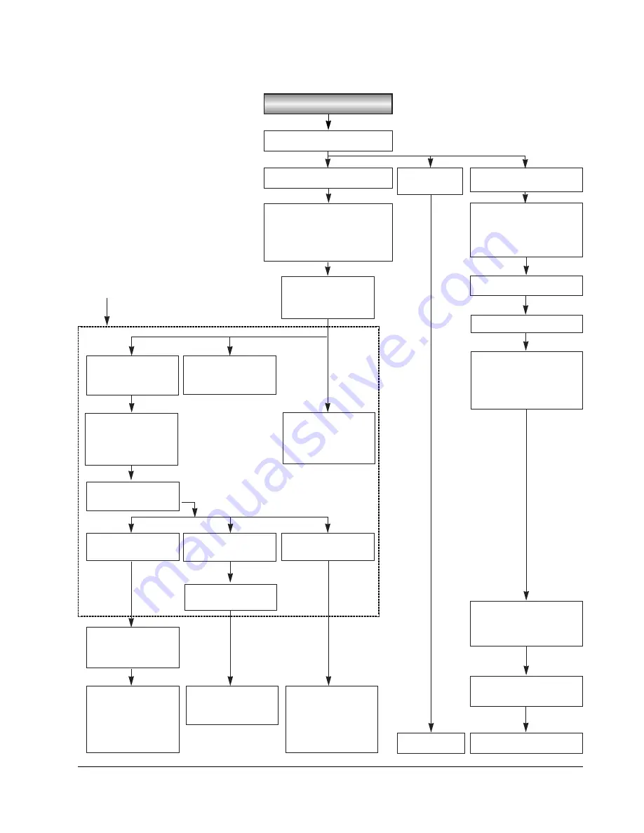
7-4-2 Loading
Cassette in
Housing down.
Motor Loading rotates.
Drum rotates
forward.
Chassis Sub moves in
direction of arrow.
Gear Worm Loading
Gear Loading
Gear Wheel Motor
Switch Mode
Gear Cam Main rotates.
Motor Capstan rotates
in reverse.
Gear Capstan, Belt Timing,
Gear Pully and Gear ldler
rotates.
Reel S rotates.
Motor Capstan rotates
forward slightly (for shifting
idler to Reel T) and stops.
Chassis Sub stops at
Loading-complete
position and contacts
rail of Main Chassis.
Arm Loading S,T move in
direction of arrows and
Pole Base S, T Slide
Arm Tension, Arm
Review and Arm Pinch
Roller shift.
Slider Main moves to
left.
Brake sub S assy
released
Pinch Roller attaches to
Capstan Shaft.
Pole Base S, T attach to
base Drum
Motor Capstan rotates
back.ward silghtly and
forward.
Arm Pinch Roller is
rotated by Silder Main
and Pinch Roller
detaches from Capstan
Shaft.
Arm Tension rotates in
direction of arrow
slightly, and Lever Brake
S, Brake Main T contact
Reel for braking
Motor Loading rotates in
reverse and then stops.
Drum stops.
Motor Capstan stops.
* This operation makes tape loading.
Motor Loading stops
slightly and then rotates
forward
Motor Loading stops
Reel S rotates counterclockwise
slightly, and then Reel
Pinch Roller rotates
Backward and then
forward
Motor Castan stops
Summary of Contents for VP-L900
Page 5: ...Product Specification 2 2 MEMO ...
Page 51: ...4 18 Disassembly and Reassembly Samsung Electronics MEMO ...
Page 79: ...5 28 Alignment and Adjustments Samsung Electronics MEMO ...
Page 109: ...Circuit Operating Description 6 30 Samsung Electronics MEMO ...
Page 124: ...Deck Operating Description Samsung Electronics 7 15 Fig 7 14 ...
Page 126: ...Deck Operating Description Samsung Electronics 7 17 Fig 7 16 ...
Page 128: ...Deck Operating Description Samsung Electronics 7 19 Fig 7 17 ...
Page 130: ...Deck Operating Description Samsung Electronics 7 21 Fig 7 18 ...
Page 132: ...Deck Operating Description Samsung Electronics 7 23 Fig 7 19 ...
Page 134: ...Deck Operating Description Samsung Electronics 7 25 Fig 7 20 ...
Page 136: ...Deck Operating Description Samsung Electronics 7 27 Fig 7 21 ...
Page 138: ...Deck Operating Description Samsung Electronics 7 29 Fig 7 22 ...
Page 139: ...Deck Operating Description 7 30 Samsung Electronics MEMO ...
Page 142: ...Samsung Electronics 10 1 10 Wiring Diagram ...
Page 143: ...Wiring Diagram 10 2 Samsung Electronics MEMO ...
Page 145: ...PCB Diagrams 11 2 Samsung Electronics COMPONENT SIDE 11 1 Main PCB ...
Page 146: ...PCB Diagrams Samsung Electronics 11 3 CONDUCTOR SIDE ...
Page 149: ...PCB Diagrams 11 6 Samsung Electronics 11 6 Front PCB 11 7 Function PCB ...


