Operating Instructions
Samsung Electronics
3-9
Basic Shooting
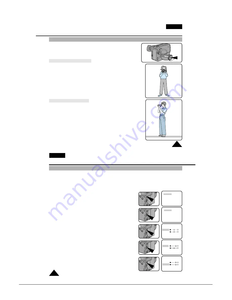
Tips for Stable recording
ENGLISH
25
■
While recording, it is very important to hold the camcorder correctly.
■
When recording, clip the LENS cover on the hand strap to avoid
the risk of the lens cover swinging into shot. (refer to figure)
Recording with the LCD Screen
1. Hold the camcorder firmly using the hand strap. (see page 16)
2. Place your right elbow against your side.
3. Place your left hand under or next to the LCD to support and adjust it.
Do not touch the built-in microphone.
4. Choose a comfortable, stable position for the shots.
You can lean against a wall or on a table for greater stability.
Do not forget to breathe gently.
5. Use the LCD frame as a guide to determine the horizontal plane.
6. Whenever possible, use a tripod.
Recording with the Viewfinder
1. Hold the camcorder firmly with the hand strap. (see page 16)
2. Place your right elbow against your side.
3. Place your left hand under the camcorder to support it.
Be sure to not touch the built-in microphone.
4. Choose a comfortable, stable position for the shots.
You can lean against a wall or on a table for greater stability.
Do not forget to breathe gently.
5. Put your eye firmly against the viewfinder.
6. Use the viewfinder frame as a guide to determine the horizontal plane.
7. Whenever possible, use a tripod.
Basic Shooting
Adjusting the LCD
ENGLISH
26
✤
You can view the image you are recording or watch a playback of recordings made by using your camcorder’s
2.5 inch colour Liquid Crystal Display (LCD) screen.
✤
Under curtain conditions you may need to adjust the settings for the LCD Screen (outdoors for example).
Adjustment can be made to the:
■
Brightness
■
Colour
1. Make sure that the battery pack is in place.
2. Set power switch to CAMERA mode. (see page 18)
3. Open the LCD Screen, the LCD will come on.
4. Press the MENU ON/OFF button, the MENU list will be displayed.
5. Turn the UP/DOWN dial until LCD ADJUST is highlighted.
6. Press ENTER.
■
The LCD ADJUST MENU will appear.
7. Turn the UP/DOWN dial to adjust the LCD brightness.
8. Press ENTER.
■
The cursor will move to the next item.
MENU
LCD ADJUST
DIS ............................OFF
D.ZOOM....................OFF
WHITE BAL. ............AUTO
DISPLAY ...................ON
LANGUAGE ..............ENGLISH
WL.REMOCON .........ON
NEXT: MENU
MENU
LCD ADJUST
DIS ............................OFF
D.ZOOM....................OFF
WHITE BAL. ............AUTO
DISPLAY ...................ON
LANGUAGE ..............ENGLISH
WL.REMOCON .........ON
NEXT: MENU
LCD ADJUST
[17]
BRIGHT
COLOUR
[17]
EXIT: MENU
LCD ADJUST
[20]
BRIGHT
COLOUR
[17]
EXIT: MENU
LCD ADJUST
[20]
BRIGHT
COLOUR
[20]
EXIT: MENU
Summary of Contents for VP-L900
Page 5: ...Product Specification 2 2 MEMO ...
Page 51: ...4 18 Disassembly and Reassembly Samsung Electronics MEMO ...
Page 79: ...5 28 Alignment and Adjustments Samsung Electronics MEMO ...
Page 109: ...Circuit Operating Description 6 30 Samsung Electronics MEMO ...
Page 124: ...Deck Operating Description Samsung Electronics 7 15 Fig 7 14 ...
Page 126: ...Deck Operating Description Samsung Electronics 7 17 Fig 7 16 ...
Page 128: ...Deck Operating Description Samsung Electronics 7 19 Fig 7 17 ...
Page 130: ...Deck Operating Description Samsung Electronics 7 21 Fig 7 18 ...
Page 132: ...Deck Operating Description Samsung Electronics 7 23 Fig 7 19 ...
Page 134: ...Deck Operating Description Samsung Electronics 7 25 Fig 7 20 ...
Page 136: ...Deck Operating Description Samsung Electronics 7 27 Fig 7 21 ...
Page 138: ...Deck Operating Description Samsung Electronics 7 29 Fig 7 22 ...
Page 139: ...Deck Operating Description 7 30 Samsung Electronics MEMO ...
Page 142: ...Samsung Electronics 10 1 10 Wiring Diagram ...
Page 143: ...Wiring Diagram 10 2 Samsung Electronics MEMO ...
Page 145: ...PCB Diagrams 11 2 Samsung Electronics COMPONENT SIDE 11 1 Main PCB ...
Page 146: ...PCB Diagrams Samsung Electronics 11 3 CONDUCTOR SIDE ...
Page 149: ...PCB Diagrams 11 6 Samsung Electronics 11 6 Front PCB 11 7 Function PCB ...


