Hardware Manual for the PCD3 Series│Document 26/789; Version E 5│31.01.2005
Saia-Burgess
Controls Ltd.
Planning an application
Orientation guide
2-3
2
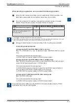
When planning an application, we recommend the following procedure:
Select the I/O modules according to your requirements. Where possible, use
PCD3 I/O modules with 16 connections; these have 16 red LEDs.
From the number of I/O modules, calculate the required number of module
holders. Check that the number of module holders is allowed:
PCD3
M3020
M3230
M3330
M5440
M5540
I/O bus connection for expansion
units
no
Yes
Number of inputs/outputs or I/O
module sockets
64
1)
4
1023
1) 2)
64
1) Using digital I/O modules PCD3.E16x or A46x with 16 I/Os each
2) On all PCD3 units, address 255 is reserved for the watchdog. The I/Os reserved for the watchdog cannot be used,
and no analogue and H modules can be used on the sockets with base address 240
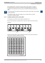
Arrange module holders in row(s) according to the mounting area avaliable
Connecting material required
Arrangement with one PCD3.Mxx0; LIOs in one row
Max. 15 x PCD3.LIO’s in a row, no extension cable, with PCD3.K010 connector
only
Connecting material for this arrangement:
n x PCD3.K010 connectors between PCD3 module holders
Arrangement with one PCD3.Mxx0; LIOs in multiple rows
Max. 3 PCD3.LIOs side-by-side and one row beneath the other, with extension
cables for the rows beneath (max. 15 PCD3.LIOs)
Connecting material for this arrangement:
n x PCD3.K106 extension cables to connect the last PCD3 module holder in
one row with the first PCD3 module holder in the next row
n x PCD3.K010 connectors between PCD3 module holders
Arrangement of a RIO node with the LIOs side-by-side
Max. 3 x PCD3.LIOs total
Connecting material for this arrangement:
n x PCD3.K010 connectors between PCD3 module holders
For all arrangements: After every five PCD3.C100 module holders, insert a PCD3.
C200 base unit as an I/O bus amplifier


