Hardware Manual for the PCD3 Series│Document 26/789; Version E 5│31.01.2005
Saia-Burgess
Controls Ltd.
Connections to the PCD3.Mxxx0
PCD3.Mxxx0 Classic CPUs and expansion housings
3-17
3
3.10
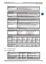
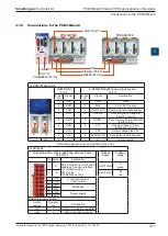
Connections to the PCD3.Mxxx0
For PCD3.M5xx0 only
RS232/PGU
Port 0
S-Net / MPI / RS 485 (9-pole D-Sub socket)
Port 10
D-Sub
pin
Signal
D-Sub
pin
Signal
Explanation
1
DCD
1
GND
GND
2
RXD
2
M24
0 V of 24 V supply
3
TXD
3
RxD/TxD-P
1
)
Receive/transmit data positive
4
DTR
4
CNTR-P
Control signal for repeater
(direction control)
5
GND
5
DGND
1
)
Date communication potential
(earth to 5 V)
6
DSR
6
VP
1
)
Supply voltage to P line
termination resistors
7
RTS
7
P24
Output voltage plus 24 V
8
CTS
8
RxD/TxD-N
1
)
Receive/send data negative
9
n.c.
9
n.c.
not connected
Port 0
Port 10
1)
Mandatory signals (must be provided by the user)
For all types
Terminal block for supply, watchdog, interrupt inputs
and Port 2
Profibus
signal
Profibus
wiring
Pin Signal
Explanation
1
D
Port 2;
RS485 up to 115 kbps
usable as free user interface
or Profi-S-Bus up to
187.5 kbps
(PCD3.M3xxx only)
RxD/TxD-N
A
green
2
/D
RxD/TxD-P
B
red
3
Int0
2 interrupt inputs or
1 fast counter
4
Int1
5
WD
Watchdog
6
WD
7
+24V
Power supply
8
GND
RS485 terminator switch
Switch
position
Designa-
tion
Explanation
left
O
without termination resistors
right
C
with termination resistors
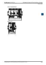
USB
Ethernet (Port 9)
RS485 (Port 2)
Slot 0 (Port 1)
S-Net/MPI
(Port 10)
PGU/RS232 (Port 0)
PCD3.M5540
PCD3.M3330

