Saia-Burgess
Controls Ltd.
Hardware Manual for the PCD3 Series│Document 26/789; Version E 5│31.01.2005
Hardware
PCD3.W4x0
5-61
5
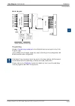
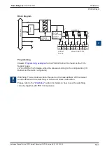
Block diagram
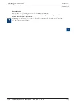
Programming
Classic:
Programming examples
for the PCD3.W4x0 will be found on the TCS-
Support page.
xx7 and RIO’s: the firmware writes the values according to the configuration (I/O
Builder and Network configurator).
Watchdog: These modules cannot be used on the base address 240 because it
would interact with the watchdog, which would cause malfunction.
Please refer to the
“Watchdog”
section for details on how to use the watchdog
correctly together with PCD3 components.
I/O
B
us
D A
D A
D A
D A
0
1
2
3
P
C
D
B
us
VOLTAGE
REFERENCE
DATA
WRITE
ADDR
V +
+ 5 V
GND
VOLTAGE
CONTROLLED
CURRENT
SOURCE
A0
A1
A2
A3
9
8
7
6
5
4
3
2
1
0
V
C
JUMPER J2
V
C
SUPPLY
24 VDC
ANALOG OUTPUTS


