Saia-Burgess
Controls Ltd.
Hardware Manual for the PCD3 Series│Document 26/789; Version E 5│31.01.2005
Communication interfaces
4
4-12
Serial interfaces on I/O module Slot 0
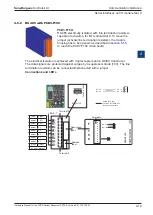
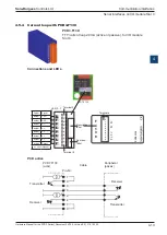
4.5.3 RS 232 with PCD3.F121 (suitable for modem)
PCD3.F121:
RS 232 with RTS/CTS, DTR/DSR, DCD, suitable for mo-
dem connection, for I/O module Slot 0.
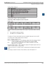
Connections and LEDs
See also manual 26/795, “PCD7.D23x Series graphic terminals”
PCD7.F121
PCD3.F121
0
1
2
3
4
5
6
7
8
9
LED 0...7
1
2
1
0
1
2
3
4
5
6
7
F
PGND
TXD
RXD
RTS
CTS
PGND
DTR
DSR
Reserve
DCD
PGND
TXD
RXD
RTS
CTS
PGND
DTR
DSR
Reserve
DCD
PGND
TX
RX
RTS
CTS
SGND
DTR
DSR
DCD
cable
Peripherie
device (DTE)
D-Sub w.
9 pol.
D-Sub w.
9 pol.
(e.g. PC)
1
2
3
4
5
6
7
8
9
8
20
7
1
2
3
4
5
6
2
3
5
7
4
6
8
D-Sub w.
25 pol.
(e.g. PC)
PGND
TXD
RXD
RTS
CTS
PGND
DTR
DSR
Reserve
DCD
PGND
TX
RX
RTS
CTS
SGND
DTR
DSR
DCD
cable
Modem
(ETCD) DCE
D-Sub w.
25 pol.
(e.g. Zyxel)
2
20
4
5
3
7
6
8
�����������������������������������
Terminal 0
Description-
label
Address-
label
Terminal 9
Terminals
Colour
Signal
amber
TXD
amber
RXD
amber
RTS
amber
CTS
amber
DTR.
amber
DSR
amber
DCD
green
Detect


