

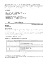


EXAMPLE
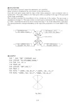
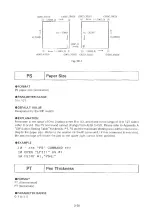
10 '
*** LT COMMAND
***
20
#1
,
"LT5
;"
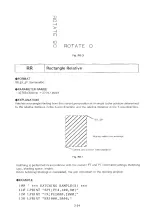
30 P R I N T # 1 , " S P l ;P R ; P D 2 0 0 0 , 0 , 0 , 1 0 0 0 , - 2 0 0 0 ,0 , 0 , - 1 0 0 0 ; PU;"
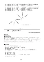
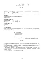
Fig. LT-2
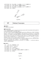
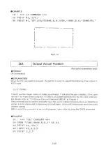
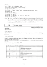
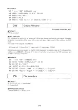
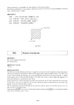
OA
Output Actual Position
(For serial connection only)
FORMAT
OA [terminator]
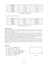
EXPLANATION
When the OA command is received, the plotter is ready to output the following three values in
ASCI! code.
X,Y,P [TERM]
X and Y are the integer values of plotter coordinates. P indicates the pen condition, 0 for a pen
up and 1 for a pen down condition. [TERM] is an output terminator for the RS-232C interface.
For details, refer to “ 5.4 Device Control Command ESC.M” in Chapter 5.
This command can be used to manually move the pen to
a
desired position where a character or
pattern is to be drawn and to determine its coordinates, which will facilitate pen positioning and
window setting.
Before using the command in an actual program, open a file by using the OPEN statement.
• EXAMPLE
10 '
*** "OA" COMMAND ***
20 OPEN "COM1:9600,N,8,1" AS #1
30 PRINT #1,"OA;"
40 INPUT #1
,X,
Y,P
50 PRINT X ,Y ,P
3 39
Summary of Contents for DXY-1100
Page 1: ...X Y PLOTTER DXY 1300 1200 1100 Roland DIGITAL GROUP ...
Page 2: ......
Page 3: ...X Y PLOTTER DXY 1300 1200 1100 COMMAND REFERENCE MANUAL c ...
Page 4: ......
Page 44: ......
Page 140: ......
Page 142: ......
Page 144: ......
Page 148: ......
Page 154: ......
Page 155: ......
Page 156: ...Roland DIGITAL GROUP ...