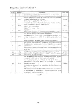
S ig n a l lin e s a re s h o w n in T a b le 5 -2 .
Pin No.
Abbrev.
Description
Plotter side
1
FG
Security line which is normally connected with the computer frame
Connected to the plotter frame
<C
om
>
2
TXD
Transmit data. Data output from the plotter to the computer. Connected
to the receive data line of the computer
SPACE
=
"0 " = +12V MARK
=
“ 1 " = -1 2 V
<
Output
>
3
RXD
Receive data. Data receive line of the plotter from the computer. Con
nected to the transmit data line of the computer
SPACE
=
"0" =
+
3V to
+
25V
MARK
= “
1
” = -
3V to - 2 5 V
<
input>
4
RTS
Request to send.
Output from the plotter to the computer. Always ON
( +
12v) is output.
<
Output
>
5
CTS
Clear to send. Input from the computer to the plotter.
When the signal line is ON ( + 3V to - 25V), the plotter is ready to out
put data, or when the line is OFF ( - 3V to -2 5 V ), no data will be out
put.
When unconnected, the plotter always operates with ON status.
<
in p u t>
6
DSR
Data set ready. Normally this line is connected with
a
signal line to in
dicate the ready-to-operate status of a modem. Input from the computer
to the plotter.
Same as for CTS when unconnected, with no problem tor the plotter in
normal use.
<lnput>
7
SG
Signal ground connected with the internal ground line in the plotter.
<Com>
14
S.TXD
Data output from the plotter to the computer in Y-connection.
<
Output>
16
S. RXD
Data receiving line in Y-connection
<
Input>
20
DTR
Data terminal ready signal to indicate that the system is ready to com
municate As in RTS, with DIP SWI-(5) set to ON (to serial).
When hardwire handshake is enabled by the ESC
the plotter con
trols DTR ON
( +
12V) or DTR OFF ( - 12V) according to the remaining
capacity of the butler.
When hardwire handshake, is sot to disable by the ESC.@ command,
DTR is always
+
12V.
DTR can be connected with CTS or DSR of the computer for handshak
ing, provided that the computer has
a
function to monitor the above
signal line and stop the data output.
<
Output>
Table 5-2
5-4
Summary of Contents for DXY-1100
Page 1: ...X Y PLOTTER DXY 1300 1200 1100 Roland DIGITAL GROUP ...
Page 2: ......
Page 3: ...X Y PLOTTER DXY 1300 1200 1100 COMMAND REFERENCE MANUAL c ...
Page 4: ......
Page 44: ......
Page 140: ......
Page 142: ......
Page 144: ......
Page 148: ......
Page 154: ......
Page 155: ......
Page 156: ...Roland DIGITAL GROUP ...

