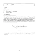

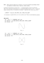


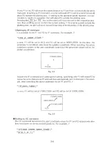
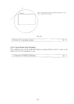

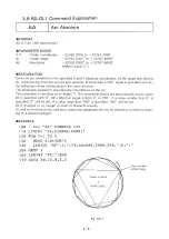
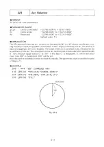


is seat, plotter coordinate P1 (1000,2000) will become user coordinate (0,0) and plotter
coordinate P2(4000,2500) will become user coordinate (1,1). (The SC command differs
from the IP command in the parameter order.) Of course, a user coordinate can also be
set outside P1 and P2 as shown in Fig. 3-4. The coordinate values in plotting from here
on will he based on this user coordinate system.
Fig. 3-4
If the SC and IP commands are executed in combination like this, the desired coordinate
can be set to the desired position. By setting values useful in plotting, the programming
load can be reduced
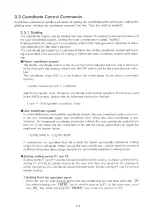
P1 and P2 input command
IP
Scaling command
SC
Paper size setting command
PS
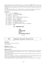
3 .3 .2 W in d o w s
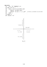
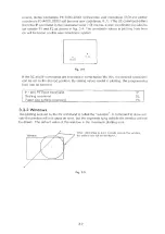
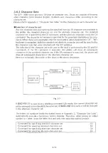
The plotting area set by the IW command is called the “ w indow” . A command to draw out
side the window will not cause an error, but the segments lying outside the window will not
be drawn, The default value o f the window is the maximum plotting area.
When attempting to draw partially outside the window,
the dotted lines will not be drawn.
Fig. 3-5
3-7
Summary of Contents for DXY-1100
Page 1: ...X Y PLOTTER DXY 1300 1200 1100 Roland DIGITAL GROUP ...
Page 2: ......
Page 3: ...X Y PLOTTER DXY 1300 1200 1100 COMMAND REFERENCE MANUAL c ...
Page 4: ......
Page 44: ......
Page 140: ......
Page 142: ......
Page 144: ......
Page 148: ......
Page 154: ......
Page 155: ......
Page 156: ...Roland DIGITAL GROUP ...


