
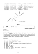


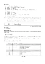
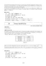


The OE command can be used to learn the error contents when the POWER/ERROR LED of the
plotter is flashed.
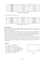
The error mask value is set to 223 by the standard or initial setting.
The IM command with no parameter or with a parameter out of the range sets the error mask
value to the standard setting value, 223.
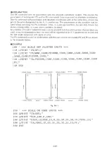
EXAMPLE
10
' * * *
IM COMMAND * * *
2 0 OPEN " LPT1
AS #1
3 0
P R I N T
#1 , "
IM 2 2 2 ; "
40
P R I N T
#1
"X X ; "
IN
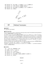
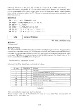
Initialize
FORMAT
IN [terminator]
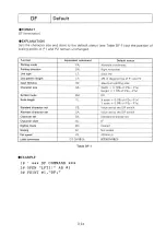
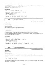
EXPLANATION
Performs the following settings in addition to the delault settings of the DF command.
(1) Pen up (PU;)
(2) Sets the scaling points to the default values (IP;)
(3) Clears any errors and the sets the third bit of the status byte
(4) Sets the rotate coordinate system to the default values (RO;)
EXAMPLE
10 '
*** IN COMMAND ***
20 O P E N " L P T 1 :" AS #1
30 P R I N T # 1 , " I N ; "
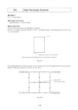
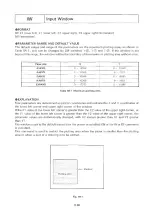
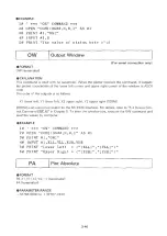
IP
Input P1 and P2
FORMAT
IP P1x,P1y (,P2x,P2y) [terminator]
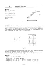
PARAMETER RANGE AND DEFAULT VALUE
The parameter range will be the range of the maximum plotting area, as shown in Table IP- 1,
that can be changed by DIP switches 1-(6), 1-
(7)
and 1-(8).
Decimal fractions are rounded down and values that are not included in Table IP-1 will be con
sidered errors.
3-34
Summary of Contents for DXY-1100
Page 1: ...X Y PLOTTER DXY 1300 1200 1100 Roland DIGITAL GROUP ...
Page 2: ......
Page 3: ...X Y PLOTTER DXY 1300 1200 1100 COMMAND REFERENCE MANUAL c ...
Page 4: ......
Page 44: ......
Page 140: ......
Page 142: ......
Page 144: ......
Page 148: ......
Page 154: ......
Page 155: ......
Page 156: ...Roland DIGITAL GROUP ...


