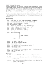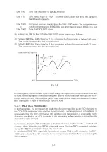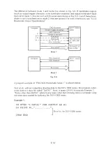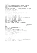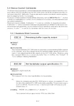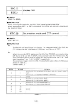
ESC.Z
ESC.)
Plotter OFF
• F O R M A T
[ESC] .Z or [ESC].)
• EXPLANATION
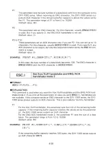
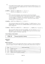
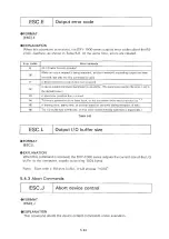
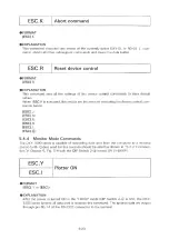
When receiving this com m and, the D X Y -1000 series ignores further data.
When receiving the ESC.Y or ESC.( com m ands, this plotter will execute a drawing with
the data that follow .
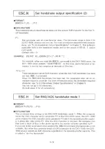
ESC.@
Set m onitor mode and DTR control
• FORMAT
[ESC].@ P1;P2:
• EXPLANATION
P1:
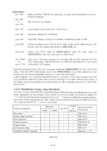
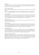
This sets the size of the plo tte r's I/O buffer. The parameter range is 0 to 9999, but
if it is larger than the initial value of 1024 then it will be set to 1024.
P2:
When the control of DTR signals (pin N o . 20 of the RS-232C connector) and the
DIP Switch 2-(4) are ON (Y-DROP), this param eter sets the m onitor mode. For
more inform ation about the DTR signals and the m onitor mode, see “ 5.3.1 Hard
ware Handshake” and “ 5 .2 .2 Y-DROP” , respectively.
The parameter range is from 0 to 255. The param eter value is the sum of bit values
shown in Table 5-7.
(Default value: 1)
Bit No.
Bit value
Contents
0
1
W hen this bit is 0, no hardw are handshake is done. DTR signal is always at
“ H ig h ” .
W hen this bit is 1, hardw are handshake is perform ed.
1
2
Ignored
2
4
W hen this bit is 0, sets m on itor m ode 1
W hen this bit is 1, sets m on itor m ode 2.
3
8
W hen this bit is 0, turns m on itor m ode OFF
W hen this bit is 1, turns m on itor m ode ON.
4
5
6
7
16
32
64
128
_______________
Ignored.
Table 5-7
5-24
Summary of Contents for DXY-1100
Page 1: ...X Y PLOTTER DXY 1300 1200 1100 Roland DIGITAL GROUP ...
Page 2: ......
Page 3: ...X Y PLOTTER DXY 1300 1200 1100 COMMAND REFERENCE MANUAL c ...
Page 4: ......
Page 44: ......
Page 140: ......
Page 142: ......
Page 144: ......
Page 148: ......
Page 154: ......
Page 155: ......
Page 156: ...Roland DIGITAL GROUP ...


