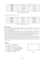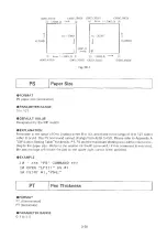
Paper size
X
Y
A 3(ISO)
0 ~ 16158
0 ~ 11040
A 4 (ISO)
0 ~ 11040
0 ~ 7721
B(ANSI)
0 ~
16640
0 ~
10365
A(ANSI)
0 ~
10365
0 ~
7962
EXPAND
0 ~
17272
0 ~
11880
Table IP-1 M axim um plotting area
Default values vary with drawing size.
Paper size
P1x,P1y
P2x,P2y
A3(ISO)
1
70,602
15370,10602
A4(ISO)
603,521
10603,7721
BIANSI)
522,259
15722,10259
A (ANSI)
250,596
10250.7796
Table IP-2 D efault values of P1, P2
EXPLANATION
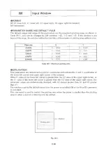
The coordinates of P1 and P2 are specified in plotter coordinates. Therefore, the X and Y coor
dinates must be within the range shown in Table IP -1 in order to insure that P1 and P2 are within
the maximum plotting area.
The IP command without parameters sets P1 and P2 to the initial values shown in the Table IP-2
The IP command is used to set P1 and P2 to given values or reset them to the initial values. P1
and P2 (the scaling points) serve to determine the positional relationship between the plotter
coordinate system inherent in the plotter and the user coordinate system whose scale is provid
ed by the user. The user coordinate scale is specified by the SC command.
If the IP command is executed with P2x and P2y omitted, P2x and P2y are moved automatically
the same distance that P1x and P ly are moved- That is, the value P2x — P1x and P2y — P1y
become the same after execution of the IP command as before execution of the IP command.
However, if P1 is set so that P2 falls outside the plotting area, an error will occur and the value
will be ignored.
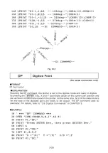
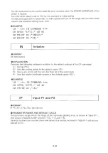
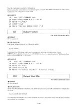
EXAMPLE
10 '
* * * IP C O M M A N D ** *
20 OPEN "LPTl:" AS #1
30 PRINT #1,"IN;SP1;PA0,0;"
40 PRINT #1,"IP0,0,2000,1000;"
50 PRINT #1,"SC0,100,0,100;"
60 PRINT #1,"EA100,100;"
70 PRINT #1,"SP0; "
3 -3 5
Summary of Contents for DXY-1100
Page 1: ...X Y PLOTTER DXY 1300 1200 1100 Roland DIGITAL GROUP ...
Page 2: ......
Page 3: ...X Y PLOTTER DXY 1300 1200 1100 COMMAND REFERENCE MANUAL c ...
Page 4: ......
Page 44: ......
Page 140: ......
Page 142: ......
Page 144: ......
Page 148: ......
Page 154: ......
Page 155: ......
Page 156: ...Roland DIGITAL GROUP ...

