Rohde & Schwarz R&S FSV Quick Start Manual Download Page 77

Preparing for Use

R&S

®

 FSVA/FSV

54

Quick Start Guide 1321.3066.02 ─ 05

Deactivating Display Power Save

► In the "Display Setup" submenu, press the "Display Pwr Save On/Off" softkey

again.
"Off" is highlighted and the power save mode is switched off.

3.4.7

Selecting and Configuring Printers

You can printout your measurement results using a local printer or a network
printer. The instrument supports two independent printout settings. This allows
you to quickly switch between output to a file and a printer.

3.4.7.1

Configuring the Printer and the Printout

1. Press the PRINT key.

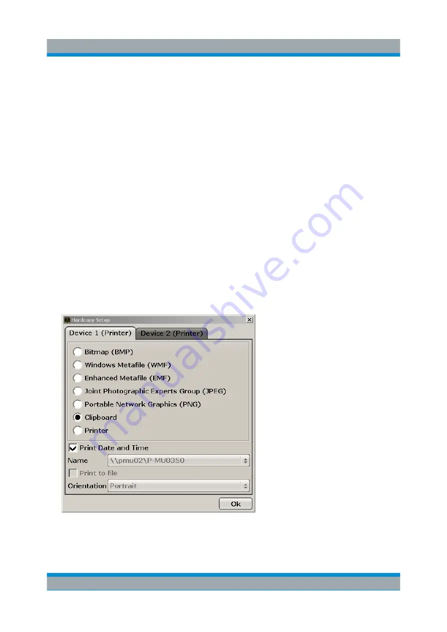
2. Press the "Device Setup" softkey.

The "Hardcopy Setup" dialog box is displayed.

3. To change the tab in order to define the second print setting, press the tab on

the screen.

4. Define the output by selecting the required options.


R&S


FSVA/FSV Setup

Summary of Contents for R&S FSV

Page 1: ...R S FSVA FSV Signal and Spectrum Analyzer Quick Start Guide Quick Start Guide 1321 3066 02 05 ENÐ2 Test Measurement ...

Page 2: ...1 5 Notes for Users of R S FSV 1307 9002Kxx Models on page 12 R S FSV3 1307 9002K03 R S FSV7 1307 9002K07 R S FSV13 1307 9002K13 R S FSV30 1307 9002K30 R S FSV40 1307 9002K39 1307 9002K40 2016 Rohde Schwarz GmbH Co KG Mühldorfstr 15 81671 München Germany Phone 49 89 41 29 0 Fax 49 89 41 29 12 164 Email info rohde schwarz com Internet www rohde schwarz com Subject to change Data without tolerance l...

Page 3: ...y to use the product in an appropriate manner This product is designed for use solely in industrial and laboratory environments or if expressly permitted also in the field and must not be used in any way that may cause personal injury or property damage You are responsible if the product is used for any purpose other than its designated purpose or in disregard of the manufacturer s instructions Th...

Page 4: ...y labels on products The following safety labels are used on products to warn against risks and dangers Symbol Meaning Symbol Meaning Notice general danger location Observe product documentation ON OFF Power Caution when handling heavy equipment Standby indication Danger of electric shock Direct current DC Caution Hot surface Alternating current AC Protective conductor terminal To identify any ter...

Page 5: ...uld result in death or serious injury Indicates a hazardous situation which if not avoided could result in minor or moderate injury Indicates information considered important but not hazard related e g messages relating to property damage In the product documentation the word ATTENTION is used synonymously These signal words are in accordance with the standard definition for civil applications in ...

Page 6: ...y are unsuitable for this purpose Always follow the manufacturer s installation instructions when installing the product and fastening it to objects or structures e g walls and shelves An installation that is not carried out as described in the product documentation could result in personal injury or even death 3 Do not place the product on heat generating devices such as radiators or fan heaters ...

Page 7: ...roper operating condition By taking appropriate safety measures and carefully laying the power cable ensure that the cable cannot be damaged and that no one can be hurt by for example tripping over the cable or suffering an electric shock 6 The product may be operated only from TN TT supply networks fuse protected with max 16 A higher fuse only after consulting with the Rohde Schwarz group of comp...

Page 8: ...ified otherwise products are not liquid proof see also section Operating states and operating positions item 1 Therefore the equipment must be protected against penetration by liquids If the necessary precautions are not taken the user may suffer electric shock or the product itself may be damaged which can also lead to personal injury 17 Never use the product under conditions in which condensatio...

Page 9: ...t the potential danger 6 Should a fire occur the product may release hazardous substances gases fluids etc that can cause health problems Therefore suitable measures must be taken e g protective masks and protective clothing must be worn 7 Laser products are given warning labels that are standardized according to their laser class Lasers can cause biological harm due to the properties of their rad...

Page 10: ...nd rechargeable batteries cells If the information regarding batteries and rechargeable batteries cells is not observed either at all or to the extent necessary product users may be exposed to the risk of explosions fire and or serious personal injury and in some cases death Batteries and rechargeable batteries with alkaline electrolytes e g lithium cells must be handled in accordance with the EN ...

Page 11: ...r on the means of transport or lifting Observe the safety regulations of the manufacturer of the means of transport or lifting Noncompliance can result in personal injury or material damage 3 If you use the product in a vehicle it is the sole responsibility of the driver to drive the vehicle safely and properly The manufacturer assumes no responsibility for accidents or collisions Never use the pr...

Page 12: ...nmental damage For additional information about environmental protection visit the Rohde Schwarz website Instrucciones de seguridad elementales Es imprescindible leer y cumplir las siguientes instrucciones e informaciones de seguridad El principio del grupo de empresas Rohde Schwarz consiste en tener nuestros productos siempre al día con los estándares de seguridad y de ofrecer a nuestros clientes...

Page 13: ...r personal especializado o personas instruidas en profundidad con las capacidades correspondientes Si fuera necesaria indumentaria de seguridad para el uso de productos de Rohde Schwarz encontraría la información debida en la documentación del producto en el capítulo correspondiente Guarde bien las informaciones de seguridad elementales así como la documentación del producto y entréguelas a usuari...

Page 14: ...tinua DC Advertencia superficie caliente Corriente alterna AC Conexión a conductor de protección Corriente continua Corriente alterna DC AC Conexión a tierra El aparato está protegido en su totalidad por un aislamiento doble reforzado Conexión a masa Distintivo de la UE para baterías y acumuladores Más información en la sección Eliminación protección del medio ambiente punto 1 Aviso Cuidado en el ...

Page 15: ...eligro p ej avisos sobre posibles daños materiales En la documentación del producto se emplea de forma sinónima el término CUIDADO Las palabras de señal corresponden a la definición habitual para aplicaciones civiles en el área económica europea Pueden existir definiciones diferentes a esta definición en otras áreas económicas o en aplicaciones militares Por eso se deberá tener en cuenta que las p...

Page 16: ...ficies vehículos estantes o mesas que por sus características de peso o de estabilidad no sean aptos para él Siga siempre las instrucciones de instalación del fabricante cuando instale y asegure el producto en objetos o estructuras p ej paredes y estantes Si se realiza la instalación de modo distinto al indicado en la documentación del producto se pueden causar lesiones o en determinadas circunsta...

Page 17: ...tores o electrónicos no son aptos para el corte de la red eléctrica Si se integran productos sin interruptor en bastidores o instalaciones se deberá colocar el interruptor en el nivel de la instalación 5 No utilice nunca el producto si está dañado el cable de conexión a red Compruebe regularmente el correcto estado de los cables de conexión a red Asegúrese mediante las medidas de protección y de i...

Page 18: ...bida p ej a una caída del rayo mediante los correspondientes sistemas de protección Si no el personal que lo utilice quedará expuesto al peligro de choque eléctrico 15 No debe introducirse en los orificios de la caja del aparato ningún objeto que no esté destinado a ello Esto puede producir cortocircuitos en el producto y o puede causar choques eléctricos fuego o lesiones 16 Salvo indicación contr...

Page 19: ...estornudos continuos enrojecimiento de la conjuntiva o dificultades respiratorias debe avisarse inmediatamente a un médico para investigar las causas y evitar cualquier molestia o daño a la salud 4 Antes de la manipulación mecánica y o térmica o el desmontaje del producto debe tenerse en cuenta imprescindiblemente el capítulo Eliminación protección del medio ambiente punto 1 5 Ciertos productos co...

Page 20: ...icas en entornos residenciales debido a posibles perturbaciones guiadas o radiadas En este caso se le podrá solicitar al operador que tome las medidas adecuadas para eliminar estas perturbaciones Aparato de clase B Aparato adecuado para su uso en entornos residenciales así como en aquellos conectados directamente a una red de distribución de baja tensión que suministra corriente a edificios reside...

Page 21: ...sus embalajes originales hasta el momento en que vayan a utilizarse 4 Las celdas o baterías no deben someterse a impactos mecánicos fuertes indebidos 5 En caso de falta de estanqueidad de una celda el líquido vertido no debe entrar en contacto con la piel ni los ojos Si se produce contacto lavar con agua abundante la zona afectada y avisar a un médico 6 En caso de cambio o recarga inadecuados las ...

Page 22: ...ión del medio ambiente 1 Los dispositivos marcados contienen una batería o un acumulador que no se debe desechar con los residuos domésticos sin clasificar sino que debe ser recogido por separado La eliminación se debe efectuar exclusivamente a través de un punto de recogida apropiado o del servicio de atención al cliente de Rohde Schwarz 2 Los dispositivos eléctricos usados no se deben desechar c...

Page 23: ...se en cuenta las indicaciones de seguridad del fabricante de dichas sustancias y las normas regionales de eliminación de residuos Tenga en cuenta también en caso necesario las indicaciones de seguridad especiales contenidas en la documentación del producto La eliminación incorrecta de sustancias peligrosas o combustibles puede causar daños a la salud o daños al medio ambiente Se puede encontrar má...

Page 24: ...rument up to date and to be informed about new application notes related to your instrument please send an e mail to the Customer Support Center stating your instrument and your wish We will take care that you will get the right information Europe Africa Middle East Phone 49 89 4129 12345 customersupport rohde schwarz com North America Phone 1 888 TEST RSA 1 888 837 8772 customer support rsa rohde...

Page 25: ......

Page 26: ... 2 1 Front Panel View 14 2 2 Rear Panel View 25 3 Preparing for Use 32 3 1 Putting into Operation 32 3 2 Connecting USB Devices 44 3 3 Connecting an External Monitor 46 3 4 R S FSVA FSV Setup 46 3 5 Windows Operating System 56 3 6 Setting Up a Network LAN Connection 60 3 7 LXI Configuration 67 3 8 Configuring the GPIB Interface 73 4 Firmware Update and Installation of Firmware Options 75 4 1 Firmw...

Page 27: ...ith Multiple Signals 121 6 4 Measurements in Zero Span 128 6 5 Storing and Loading Instrument Settings 140 7 Brief Introduction to Remote Control 143 7 1 Basic Steps in Remote Control Programming 143 7 2 Detailed Programming Examples 151 8 Appendix LAN Interface 167 8 1 Configuring the Network 167 8 2 Operation with Windows Remote Desktop 175 8 3 Operation with a VNC Client 178 8 4 Starting and Te...

Page 28: ...complete information for the base unit and the software options directly on the instrument Operating manuals Separate manuals for the base unit and the software options are provided for download Base unit manual Contains the description of the graphical user interface an introduction to remote control the description of all SCPI remote control commands pro gramming examples and information on main...

Page 29: ... the instrument Data sheet and brochure The data sheet contains the technical specifications of the R S FSVA FSV It also lists the options and their order numbers as well as optional accessories The brochure provides an overview of the instrument and deals with the specific characteristics See www rohde schwarz com brochure datasheet FSV Release notes and open source acknowledgment OSA The release...

Page 30: ...losed by quotation marks 1 2 2 Conventions for Procedure Descriptions When describing how to operate the instrument several alternative methods may be available to perform the same task In this case the procedure using the touchscreen is described Any elements that can be activated by touching can also be clicked using an additionally connected mouse The alternative procedure using the keys on the...

Page 31: ...nction is displayed For standard Windows dialog boxes e g File Properties Print dialog etc no context sensitive help is available If the help is already displayed press the softkey for which you want to display help A topic containing information about the softkey and its function is displayed If a softkey opens a submenu and you press the softkey a second time the submenu of the softkey is displa...

Page 32: ...ess the link text on the touchscreen Searching for a topic 1 Change to the Index tab 2 Enter the first characters of the topic you are interested in The entries starting with these characters are displayed 3 Change the focus by pressing the ENTER key 4 Select the suitable keyword by using the UP ARROW or DOWN ARROW keys or the rotary knob 5 Press the ENTER key to display the help topic The View ta...

Page 33: ...ou to undo or redo user inputs The new DISPLAY key opens a menu to configure features like enabling and disabling of the touchscreen the toolbar with icons or the soft or mini soft front panel You can also hide softkeys there The new MAXIMIZE SPLIT and CHANGE FOCUS keys can be used to move the blue focus frame in displays with diagrams and tables to enlarge the view of one of the diagrams or table...

Page 34: ...y switching between applications simply by touching the tabs 16 markers are supported and a marker table is available If tables get too large you can scroll using the touchscreen or maximize the table using the CHANGE FOCUS and MAXIMIZE SPLIT keys A wizard is available in the TRACE menu to easily set up all 6 traces at a glance Dialog boxes and input fields are on the upper right side of the displ...

Page 35: ...ds When using two ranges for a band the handover frequency can be defined freely within the overlapping frequency range also for standard bands Additional traces are available for use when using the signal identification functions Signal ID and Auto ID All available conversion loss tables are offered for selection validity tests are performed after selection 1 5 Notes for Users of R S FSV 1307 900...

Page 36: ...he bandwidth extension option R S FSV B160 1311 2015 xx is not availa ble for the R S FSV 1307 9002Kxx models The maximum usable I Q analy sis bandwidth for these models is 28 MHz or with option R S FSV B70 40 MHz Notes for Users of R S FSV 1307 9002Kxx Models ...

Page 37: ... sections 1 3 2 5 7 6 4 8 9 10 11 12 13 14 15 17 18 22 19 16 20 21 Figure 2 1 Front panel view of an R S FSVA No Description See 1 General device functions e g Change mode Setup Default Set tings Help Chapter 2 1 1 Function Keys on the Front Panel on page 16 2 USB connector for external devices e g keyboard mouse Chapter 2 1 3 Connectors on the Front Panel on page 20 3 ON OFF switch Chapter 3 1 8 ...

Page 38: ... 16 12 Numeric keyboard units and data entry keys Chapter 5 2 4 Keypad on page 90 13 Rotary knob Chapter 5 2 5 Rotary Knob on page 91 14 Arrow keys Chapter 5 2 6 Arrow Keys UNDO REDO Keys on page 91 15 Undo redo functions Chapter 5 2 6 Arrow Keys UNDO REDO Keys on page 91 16 AF output with volume control optional Chapter 2 1 4 Optional Front Panel Connec tors on page 22 17 Noise source control Cha...

Page 39: ...functions e g Reference frequency external internal noise source Date time display configuration LAN interface Self alignment Firmware update and enabling of options Information about instrument configuration incl firmware ver sion and system error messages Service support functions self test etc PRINT Customizes the printout selects and configures the printer HELP Displays the Online Help MODE Pr...

Page 40: ...r the level display Sets the level offset and the input impedance Activates the preamplifier option RF Preamplifier R S FSV B22 SCALE for special applications AUTO SET Enables automatic settings for level frequency or sweep type mode BW Sets the resolution bandwidth and the video bandwidth SWEEP Sets the sweep time and the number of measurement points Selects continuous measurement or single measu...

Page 41: ...ns MEAS Provides the measurement functions Measurement of multicarrier adjacent channel power Ch Power ACLR Carrier to noise spacing C N C No Occupied bandwidth OBW Spectrum emission mask measurement Spectrum Emission Mask Spurious emissions Spurious Emissions Measurement of time domain power Time Domain Power Signal statistics amplitude probability distribution APD and cumulative complementary di...

Page 42: ...or excessive force can damage the touchscreen Observe the following instructions when operating or cleaning the touch screen Never touch the screen with ball point pens or other pointed objects with sharp edges It is recommended that you operate the touchscreen by finger only As an alternative you can use a stylus pen with a smooth soft tip Never apply excessive force to the screen Touch it gently...

Page 43: ...h diagram specific trace information 5 Measurement results area 6 Diagram footer with diagram specific information depending on measurement mode 7 Error indicator 8 Error message if available 9 Device status 10 Progress bar for measurement 11 Date and time display 12 Softkeys for menu access 2 1 3 Connectors on the Front Panel This section describes the front connectors and interfaces of the R S F...

Page 44: ...mplifi ers and frequency converting DUTs Conventional noise sources require a voltage of 28 V in order to be switched on and 0 V to be switched off The output supports a maximum load of 100 mA 2 1 3 3 RF INPUT 50Ω The RF input is to be connected to the DUT via a cable equipped with an appro priate connector Risk of instrument damage Do not overload the input For maximum allowed values see the data...

Page 45: ...nnector The internal impedance is 10 Ω The output voltage can be set by using the volume control to the right of the female connector If a plug is connected the internal loudspeaker is automatically switched off The female connector and volume control are available only with the audio demodulator option R S FSV B3 To use the AF OUTPUT in the In Output menu INPUT OUTPUT key select Video Output The ...

Page 46: ... at the output For details refer to the data sheet Sensitive DUTs concerning matching For DUTs with sensitive RF characteristics with regard to matching VSWR at the input insert a 10 dB attenuator between the DUT and the tracking generator 2 1 4 3 Connections for External Mixers EXT MIXER Option R S FSV B21 External mixers can be connected at the LO OUT IF IN and IF IN female connec tors option R ...

Page 47: ...Three port mixer 1 Connect the LO OUT IF IN output of the R S FSVA FSV to the LO port of the external mixer 2 Connect the IF IN input of the R S FSVA FSV to the IF port of the external mixer 3 Feed the signal to be measured to the RF input of the external mixer Front Panel View ...

Page 48: ...contained in the R S FSVA FSV the IF signal can be tapped from the line which is used to feed the LO signal to the mixer 2 Feed the signal to be measured to the RF input of the external mixer 2 2 Rear Panel View Figure 2 3 shows the rear panel view of the R S FSVA FSV The individual ele ments are described in more detail in the subsequent sections Optional connec tors and interfaces are indicated ...

Page 49: ...EBAND INPUT OUTPUT connectors option B17 11 MONITOR VGA 12 REF IN 13 REF OUT 14 GPIB interface 15 AC Power Supply Connection and Main Power Switch with fuse 16 EXT REF with OCXO option B4 2 2 1 Standard Rear Panel Connectors 2 2 1 1 AC Power Supply Connection and Main Power Switch An AC power supply connector and main power switch are located in a unit on the rear panel of the instrument Main powe...

Page 50: ...air and STP for shielded twisted pair 2 2 1 3 MONITOR VGA The female VGA connector is used to connect an external monitor Step by step instructions how to connect an external monitor are provided in Chapter 3 3 Connecting an External Monitor on page 46 2 2 1 4 EXT TRIGGER GATE IN The female connector for external trigger gate input is used to control the mea surement by means of an external signal...

Page 51: ...ore details refer to chapter 7 Remote Control Basics in the Operating Manual 2 2 1 8 TRIGGER OUTPUT The female BNC connector can be used to provide a signal to another device The signal is TTL compatible 0 V 5 V The Trigger out softkey in the In Output menu INPUT OUTPUT key is used to control the trigger output 2 2 1 9 IF VIDEO The female BNC connector can be used for various outputs Intermediate ...

Page 52: ...lways terminate any connected IEC bus cables with an instrument or controller 2 2 1 11 AUX PORT The 9 pole SUB D male connector provides control signals for controlling external devices The voltage levels are of the TTL type 5 V Pin Signal Description 1 5 V max 250 mA Supply voltage for external circuits 2 to 7 I O Control lines for user ports see User manual 8 GND Ground 9 READY FOR TRIGGER Signa...

Page 53: ...e an ultra high precision reference option R S FSV B14 is available This option generates an even more precise 10 MHz reference signal with an output level of 0 dBm If instal led and if no external signal is used this signal is used as an internal refer ence also if an OCXO reference is installed It can also be used to syn chronize other connected devices via the REF OUT connector 2 2 2 2 External...

Page 54: ...rface R S FSV B17 The R S FSVA FSV Digital Baseband Interface option R S FSV B17 provides an online digital I Q data interface on the rear panel of the instrument for input and output The digital input and output can be enabled in the base unit or in one of the applications where available Rear Panel View ...

Page 55: ...k fire personal injury or damage Do not open the instrument casing Read and observe the Basic Safety Instructions at the beginning of this manual in addition to the safety instructions in the following sec tions Notice that the data sheet may specify additional operating condi tions Risk of instrument damage Note that the general safety instructions also contain information on operat ing condition...

Page 56: ...e correctly connected and are not overloaded Risk of electrostatic discharge ESD Electrostatic discharge ESD can damage the electronic components of the instrument and the device under test DUT ESD is most likely to occur when you connect or disconnect a DUT or test fixture to the instrument s test ports To prevent ESD use a wrist strap and cord and connect yourself to the ground or use a conducti...

Page 57: ...t for completeness using the delivery note and the acces sory lists for the various items 6 Check the instrument for any damage If there is damage immediately contact the carrier who delivered the instrument Make sure not to discard the box and packing material Packing material Retain the original packing material If the instrument needs to be transpor ted or shipped at a later date you can use th...

Page 58: ...feet are folded out The feet may fold in if they are not folded out completely or if the instrument is shifted This may cause damage or injury Fold the feet completely in or completely out to ensure stability of the instrument Never shift the instrument when the feet are folded out When the feet are folded out do not work under the instrument or place anything underneath The feet can break if they...

Page 59: ...erall load imposed on the lowest instrument must not exceed 500 N All instruments must have the same dimensions width and length If the instruments have foldable feet fold them in completely Rackmounting The R S FSVA FSV can be installed in a rack using a rack adapter kit for the order no see data sheet The installation instructions are part of the adapter kit Risk of instrument damage in a rack A...

Page 60: ...wer supply using the supplied power cable Since the instrument is assembled in line with the specifications for safety class EN61010 it may only be connected to an outlet that has a ground con tact 3 1 5 Changing the AC Supply Fuse Only fuses of the type IEC 60 127 T3 15H 250 V should be used Those fuses are used for all of the specified nominal AC supply voltages To change the AC supply fuses 1 D...

Page 61: ...jured due to electrical shock Before switching on the R S FSVA FSV switch on the DC power supply Switching the DC power supply on 1 Connect the R S FSVA FSV DC power supply device to the DC power source e g battery pack or vehicle as described in the option s installation guide 2 Set the switch on the DC power supply to I A green LED indicates that the DC power supply is ready for operation 3 In c...

Page 62: ...ibed in the installa tion guide Note The batteries must be charged before initial use see Chapter 3 1 7 1 Charging the Battery Pack on page 40 2 Set the switch on the battery pack to I 3 Set the switch on the DC power supply to I A green LED indicates that the DC power supply is ready for operation 4 In case of undervoltage the DC power supply switches off automatically This state is indicated by ...

Page 63: ... be used to charge all four rechargeable batteries of the R S FSVA FSV B32 battery pack simultaneously The rechargeable batteries can be charged at ambient tem peratures of 0 C to 45 C 1 Undo the knurled screws 10 on the front of the battery pack and open the flap 11 2 Pull the rechargeable batteries 12 by the tab out of the housing Figure 3 1 Battery compartment 3 Connect the power cable to the c...

Page 64: ...pleted Green LED remains lit Fault Red LED lights up 5 When charging has been completed the rechargeable batteries can be removed from the charger The LCD on the front of the rechargeable battery indicates the charge level in increments of 20 6 Insert the rechargeable batteries into the battery pack and close the flap on the front Secure the flap using the two knurled screws Putting into Operation...

Page 65: ...n the front panel After booting the instrument is ready for operation A green LED above the ON OFF key indicates this Warm up time for OCXO When the instrument is switched on the OCXO requires an extended warm up time see data sheet Switching the instrument off 1 Press the ON OFF key on the front panel 2 Change the AC power switch on the rear panel to position O or disconnect the instrument from t...

Page 66: ...Once the system correction values have been calculated successfully a mes sage is displayed To display the alignment results again later Press the SETUP key Press the Alignment softkey Press the Show Align Results softkey Performing a self test The self test does not need to be repeated every time the instrument is switched on It is only necessary when instrument malfunction is suspected 1 Press t...

Page 67: ...essary by using USB hubs Due to the large number of available USB devices there is almost no limit to the expansions that are possible with the R S FSVA FSV The following list shows various USB devices that can be useful Memory stick for easy transfer of data to from a computer e g firmware updates CD ROM drives for easy installation of firmware applications Keyboard or mouse to simplify the entry...

Page 68: ... other input methods to configure the keyboard properties To access the Windows operating system press the Windows key on the external keyboard Connecting a mouse The mouse is detected automatically when it is connected Select Start Control Panel Devices and Printers Mouse to configure the mouse properties To access the Windows operating system press the Windows key on the external keyboard Connec...

Page 69: ... 5 Press the Configure Monitor softkey The configuration of the connected monitor is determined and displayed in the standard Windows configuration dialog box 6 In the configuration dialog box you can switch from the internal monitor lap top icon to the external monitor monitor icon or both double monitor icon If the external monitor is selected the R S FSVA FSV display is disabled The screen cont...

Page 70: ...e menu is provided in the following procedure for convenience 1 Select the SETUP hardkey 2 Select the General Settings softkey 5th from the top 3 Select the Language softkey 6th from the top 4 Select an available interface language All softkeys dialog boxes input settings etc are displayed in the selected lan guage To change the default input language of an external keyboard use the stan dard Wind...

Page 71: ... and Time You can set the date and time for the internal real time clock as follows Opening the Date and Time Properties dialog box 1 Press the SETUP key 2 Press the General Setup softkey 3 Press the Time Date softkey to open the Date and Time Properties dia log box The Date Time tab is displayed Changing the date 1 Press the arrow on the Month field to display the list 2 Select the month from the...

Page 72: ... the list 4 Optionally select the Automatically adjust clock for daylight saving changes check box 5 Click OK 3 4 4 Aligning the Touchscreen When the device is delivered the touchscreen is initially aligned However it may become necessary to adjust the alignment later e g after an image update or after exchanging a hard disk If you notice that touching a specific point on the screen does not achie...

Page 73: ...g a Theme on page 109 and cannot be changed individually 3 4 5 1 Displaying the Screen Colors Submenu 1 Press the SETUP key 2 Press the Display Setup softkey 3 Press the More softkey 4 Press the Screen Colors softkey The Screen Colors submenu is displayed 3 4 5 2 Using the Default Color Settings To select the default setting for brightness tint and color saturation of all screen objects 1 In the S...

Page 74: ... Screen Colors Submenu on page 50 press the Select Screen Color Set softkey The Select Screen Color Set dialog box is displayed 2 Select the User Defined Colors option 3 In the screen colors submenu press the Select Object softkey The Screen Color Setup dialog box is displayed 4 Press the arrow on the Selected Object list and select the object for which you want to change the color setting 5 Selec...

Page 75: ...K to accept the new settings and to close the dialog box Remote command DISP CMAP1 41 PDEF color 3 4 5 4 Defining and Using a User Defined Color Set 1 In the screen colors submenu see Chapter 3 4 5 1 Displaying the Screen Colors Submenu on page 50 press the Select Screen Color Set softkey The Select Screen Color Set dialog box is displayed 2 Select the User Defined Colors option 3 In the Screen Co...

Page 76: ...e 51 8 Click OK to accept the new settings and to close the dialog box Remote command DISP CMAP1 41 HSL hue sat lum 3 4 6 Setting the Display Power Save Function The R S FSVA FSV provides a feature for automatically switching off its screen after a user defined period of time The background lighting is disabled if no entries are made from the front panel after the selected response time key soft k...

Page 77: ...asurement results using a local printer or a network printer The instrument supports two independent printout settings This allows you to quickly switch between output to a file and a printer 3 4 7 1 Configuring the Printer and the Printout 1 Press the PRINT key 2 Press the Device Setup softkey The Hardcopy Setup dialog box is displayed 3 To change the tab in order to define the second print setti...

Page 78: ...Print Date and Time option to add this information to the printout 9 Click OK to accept the settings and to close the dialog box 3 4 7 2 Selecting the Printout Colors 1 Press the PRINT key 2 Press the Colors softkey 3 To print in color press the Select Print Color Set softkey to select the color set The Select Print Color Set dialog box is displayed 4 Select the color set by using the arrow keys a...

Page 79: ...white printout press the Color On Off softkey to switch off the color In the black and white printout all background colors are printed out in white and all color lines in black This allows you to improve con trast on the printout Remote command HCOP DEV COL ON 3 5 Windows Operating System The instrument contains the Windows 7 operating system which has been config ured according to the instrument...

Page 80: ... software FileShredder for reliable deletion of files on the hard disk 3 5 1 Virus Protection Take appropriate steps to protect your instruments from infection Use strong fire wall settings and scan any removable storage device used with a Rohde Schwarz instrument regularly It is also recommended that you install anti virus software on the instrument Rohde Schwarz does NOT recommend running anti v...

Page 81: ...s active until you explicitly deactivate it or change the password For information on how to deactivate or re activate the automatic login refer to Chapter 3 5 3 1 The Automatic Login Function on page 58 Passwords For all default user accounts the initial password is 894129 Note that this pass word is very weak and it is recommended that you change the password for both users after initial login Y...

Page 82: ... started Adapting the automatic login function to a new password If you change the Instrument user s administrator s password which is used during automatic login this function no longer works You must adapt the settings for the command that activates the auto login function first 1 Open the C R_S INSTR USER NO_AUTOLOGIN REG file in any text editor e g Notepad 2 In the line DefaultPassword 894129 ...

Page 83: ...nal keyboard All necessary system settings can be defined in the Start Control Panel menu for required settings refer to the Windows 7 documentation and to the hardware description 3 5 5 Accessing the Windows Task Bar The Windows task bar also provides quick access to commonly used programs for example Paint or Wordpad IECWIN the auxiliary remote control tool provided free of charge and installed ...

Page 84: ...y user accounts with administrator rights can configure LAN net works LXI The R S FSVA FSV complies with LXI Class C LXI gives you direct access to the LAN settings described below For further information on the LXI interface refer to the LXI Configuration 3 6 1 Connecting the Instrument to the Network There are two methods to establish a LAN connection to the instrument A non dedicated network Et...

Page 85: ...cted to the LAN Windows automatically detects the net work connection and activates the required drivers The network card can be operated with a 1 GBit Ethernet IEEE 802 3u interface 3 6 2 Assigning the IP Address Depending on the network capacities the TCP IP address information for the instrument can be obtained in different ways If the network supports dynamic TCP IP configuration using the Dyn...

Page 86: ...is On the IP address of the DHCP server is obtained automatically The configuration is saved and you are prompted to restart the instrument You can skip the remaining steps Note When a DHCP server is used a new IP address may be assigned each time the instrument is restarted This address must first be determined on the instrument itself Thus when using a DHCP server it is recommended that you use ...

Page 87: ...nected in the LAN can be accessed via an unambiguous computer name instead of the IP address The DNS server translates the host name to the IP address This is especially useful when a DHCP server is used as a new IP address may be assigned each time the instrument is restarted Each instrument is delivered with an assigned computer name but this name can be changed 1 Obtain the name of your DNS dom...

Page 88: ...321 3066 02 05 5 In the Local Area Connection Status dialog box select the Properties but ton The items used by the LAN connection are displayed 6 Tap the entry named Internet Protocol Version 4 TCP IPv4 to highlight it Setting Up a Network LAN Connection ...

Page 89: ... PC or instrument connected in the LAN can be accessed via an unambiguous computer name instead of the IP address The DNS server translates the host name to the IP address This is especially useful when a DHCP server is used as a new IP address may be assigned each time the instrument is restarted Each instrument is delivered with an assigned computer name but this name can be changed The default ...

Page 90: ...gh a network Rohde Schwarz highly recommends the use of the firewall on your instrument Rohde Schwarz instruments are shipped with the Windows firewall enabled and preconfigured in such a way that all ports and connections for remote control are enabled For details and recommendations see the Rohde Schwarz White Paper 1EF96 Malware Protection Windows 10 Note that changing firewall settings require...

Page 91: ... Class C instruments shall also support automatic detection in a LAN via the VXI 11 discovery protocol and program ming by means of IVI drivers Class B adds IEEE 1588 Precision Time Protocol PTP and peer to peer communication to the base class IEEE 1588 allows all instruments on the same network to automatically synchronize to the most accurate clock availa ble and then provide time stamps or time...

Page 92: ...N configuration LAN Configuration Initialize LCI Firmware update After a firmware update shut down and re start the instrument in order to enable the full LXI functionality 3 7 1 LXI Configuration Dialog Box This dialog box provides basic LXI functions for the R S FSVA FSV LXI Config uration is a tab of the System System Configuration dialog box LXI Status Enabled switches the LXI logo in the stat...

Page 93: ... Instrument specific name Description Signal Analysis R S FSVA FSV Negotiation Auto Detect VXI 11 Discovery Enabled The LAN settings are configured using the instrument s LXI Browser Interface 3 7 2 LXI Browser Interface The instrument s LXI browser interface works correctly with all W3C compliant browsers Typing the instrument s host name or IP address in the address field of the browser on your ...

Page 94: ...equired by the LXI standard including the VISA resource string in read only format Press the Device Indicator toggle button to activate or deactivate the LXI status indication in the status bar of the R S FSVA FSV If it is active the LXI logo blinks in the status bar A green LXI status symbol indicates that a LAN connection has been established a red symbol indicates that no LAN cable is connected...

Page 95: ...ay are used to configure the LAN The automatic configu ration mode uses DHCP server or Dynamic Link Local Addressing Automatic IP to obtain the instrument IP address Changing the LAN configuration is password protected The password is LxiWebIfc notice upper and lower case characters This password cannot be changed in the current firmware version The links at the bottom of the LAN Configuration pag...

Page 96: ...cted To initiate a ping between the LXI compliant instrument and a second connected device 1 Enable ICMP Ping on the Advanced LAN Configuration page enabled after an LCI 2 Enter the IP address of the second device without the ping command and without any further parameters into the Destination Address field e g 10 113 10 203 3 Click Submit The result of the echo request is displayed if the connect...

Page 97: ... setting range is from 0 to 30 If SCPI is selected as the GPIB language the default address is 20 Remote command SYST COMM GPIB ADDR 20 Setting the default ID response string In the GPIB menu press the ID String Factory softkey to select the default response to the IDN command Setting a user defined ID response string In the GPIB menu press the ID String User softkey to enter a user defined respon...

Page 98: ... Copying the files to the instrument 1 Press the SETUP key 2 Press the More softkey 3 Press the Firmware Update softkey The Firmware Update dialog box is displayed 4 Enter the drive name and directory via the keypad Example The installation files are stored on a memory stick in the Update directory After you insert the memory stick it will be detected as drive D Therefore the required path specifi...

Page 99: ...ou want to install and click the Next button 4 Your LAN subnet is scanned and all found instruments are listed Note The FSVSetup exe command communicates with the instrument via LAN which means the command must pass the firewall Therefore add the command to your firewall rules then restart the scan by clicking Rescan 5 Select the instruments you want to update You can select up to 5 instruments to...

Page 100: ...me using the R S FSVA FSV If an option has already expired a message box appears for you to confirm In this case all instrument functions are unavailable including remote control until the R S FSVA FSV is rebooted Alternatively you can activate options using an XML file To activate firmware options using an XML file 1 Press the SETUP key 2 Press the More softkey 3 Press the Option Licenses softkey...

Page 101: ...elp It also describes the user interface elements listed in Figure 2 2 in more detail Note the Conventions Used in the Documentation concerning procedure descriptions and terminology described at the beginning of this manual 5 1 Information in the Diagram Area The following figure shows a measurement diagram during analyzer operation All different information areas are labeled They are explained i...

Page 102: ...e tab is displayed on the screen In order to switch from one channel display to another simply press the corresponding tab The icon on the tab label indicates that the displayed trace no longer matches the current instrument settings This may be the case for exam ple if a trace is frozen and the instrument settings are changed As soon as a new measurement is performed the icon disappears To start ...

Page 103: ...ffset SWT Sweep time that has been set If the sweep time does not correspond to the value for automatic coupling a bullet is displayed in front of the field The color of the bullet turns red if the sweep time is set below the value for auto matic coupling In addition the UNCAL flag is shown In this case the sweep time must be increased RBW Resolution bandwidth that has been set If the bandwidth do...

Page 104: ...surement as opposed to the common hardware settings that are always displayed The following types of information may be displayed if applicable Label Description SGL The sweep is set to single sweep mode Sweep Count The current signal count for measurement tasks that involve a specific number of subsequent sweeps see Sweep Count setting in Sweep menu in the Operating manual TRG Trigger source for ...

Page 105: ...diagram header above the diagram contains the following trace information The header may contain a user defined introductory title see Chapter 5 4 7 Adding a Title to the Diagram Header on page 109 Editing settings in the diagram header All settings that are displayed in the diagram header can easily be edited by selecting the setting in the display by tapping or clicking The correspond ing edit d...

Page 106: ...gram grid if available The value in the square brackets after the index indicates the trace to which the marker is assigned Example M1 1 defines marker 1 on trace 1 For more than 2 mark ers a separate marker table is displayed beneath the diagram If applicable the active measurement function for the marker and its main results are indicated as well The functions are indicated with the following ab...

Page 107: ...er or measurement function Mode dependant Information in Diagram Footer The diagram footer beneath the diagram contains the following information depending on the current mode Mode Label Information FREQ CF Center frequency between start and stop Span Frequency span SPAN CF 1 0 ms Zero span For most modes the number of sweep points shown in the display are indicated in the diagram footer In zoom m...

Page 108: ... used for digital input The optional Digital Baseband interface B17 is being used to provide digi tal output Error information If errors or irregularities are detected a keyword and an error message if availa ble are displayed in the status bar The following keywords are used UNCAL One of the following conditions applies Correction data has been switched off No correction values are available This...

Page 109: ...he status bar Date and time The date and time settings of the instrument are displayed in the status bar 5 2 Means of User Interaction The instrument provides a user interface for operation that does not require an external keyboard using the following means of interaction Chapter 5 2 1 Toolbar on page 87 Chapter 5 2 2 Touchscreen on page 88 Chapter 5 2 3 On screen Keyboard on page 89 Chapter 5 2 ...

Page 110: ... screen if available see Chapter 5 Basic Operations on page 78 By default this toolbar is not displayed Displaying the toolbar Press the Toolbar icon to the right of the tabs in the display to toggle the toolbar on or off Alternatively 1 Press the SETUP key 2 Press the Display Setup softkey 3 Press the Tool Bar State On Off softkey Or 4 Press the DISPLAY key 5 In the Display Settings dialog box se...

Page 111: ...ea Can be repeated several times Zoom off the diagram is displayed in its original size 5 2 2 Touchscreen A touchscreen is a screen that is touch sensitive i e it reacts in a specified way when a particular element on the screen is tapped by a finger or a pointing device for example Any user interface elements that can be clicked on by a mouse pointer can also be tapped on the screen to trigger th...

Page 112: ...entire screen DIAGRAM TOUCH OFF touchscreen is deactivated for the diagram area of the screen but active for the surrounding softkeys toolbars and menus SCPI command DISP TOUCh STAT OFF 5 2 3 On screen Keyboard The on screen keyboard is an additional means of interacting with the instrument without having to connect an external keyboard The on screen keyboard display can be switched on and off as ...

Page 113: ... GHz dBm MHz dBm kHz dB and Hz dB These keys add the selected unit to the entered numeric value and complete the entry In the case of level entries e g in dB or dimensionless values all units have the value 1 as mulitplying factor Thus they have the same function as an ENTER key The same is true for an alphanumeric entry ESC key Closes all kinds of dialog boxes if the edit mode is not active Quits...

Page 114: ...e selected option of the focused area if the edit mode is active 5 2 5 Rotary Knob The rotary knob has several functions Increments clockwise direction or decrements counter clockwise direction the instrument parameter at a defined step width in the case of a numeric entry Shifts the selection bar within focused areas e g lists if the edit mode is activated Shifts markers limit lines etc on the sc...

Page 115: ...us before the previous action is retrieved The undo function is useful for example if you are performing a zero span measurement with several markers and a limit line defined and accidentally click the ACP softkey In this case very many settings would be lost How ever if you press UNDO immediately afterwards the previous status is retrieved i e the zero span measurement and all settings The REDO k...

Page 116: ...reen When pressed it displays the next set of softkeys If the softkey label contains a symbol it represents a submenu of further softkeys When you press it the submenu is displayed The Up key switches to the next higher level of the menu The start menu of the current measurement mode is accessed directly by pressing the HOME key on the front panel Softkey actions A softkey performs one of the foll...

Page 117: ...ed for a specified time Any edit dialog boxes required for entry remain in the display 1 Press the DISPLAY key 2 In the Display Settings dialog box select Softkey Bar State Off The softkeys are no longer displayed To display the softkeys again select Softkey Bar State On Remote DISP SKEY STAT OFF 5 2 8 Context sensitive Menus Markers and traces in the display as well as the information in the chan...

Page 118: ...designed to enter a numeric value In the documentation these dialog boxes are called edit dialog boxes Dialog boxes that are not only designed for parameter entry have a more complex structure and in the documentation are called dialog boxes The navigation in Windows dialog boxes differs in some aspects from the navigation in R S FSVA FSV dialog boxes For details see Chapter 5 3 3 Navigating in Di...

Page 119: ...VA FSV Chapter 5 3 1 Entering Numeric Parameters on page 96 Chapter 5 3 2 Entering Alphanumeric Parameters on page 97 Chapter 5 3 3 Navigating in Dialog Boxes on page 99 5 3 1 Entering Numeric Parameters If a field requires numeric input the keypad provides only numbers 1 Enter the parameter value using the keypad or change the currently used parameter value by using the rotary knob small steps or...

Page 120: ...ers and special characters via the keypad 1 Press the key once to enter the first possible value 2 All characters available via this key are displayed 3 To choose another value provided by this key press the key again until your desired value is displayed 4 With every key stroke the next possible value of this key is displayed If all possible values have been displayed the series starts with the f...

Page 121: ...correction Completing the entry Press the ENTER key or the rotary knob Aborting the entry Press the ESC key The dialog box is closed without changing the settings Table 5 2 Keys for alphanumeric parameters Key name upper inscription Series of special characters and number provided 7 7 µ Ω 8 A B C 8 Ä ÆÅ Ç 9 D E F 9 É 4 G H I 4 5 J K L 5 6 M N O 6 Ň Ö 1 P Q R S 1 2 T U V 2 Ü 3 W X Y Z 3 0 blank 0 _...

Page 122: ...ple Changing the focus The focus on the graphical user interface is moved by pressing an element on the screen or via the rotary knob The focused area is marked with a blue frame see Figure 5 4 If this area consists of more than one element e g lists of options or tables you must first switch to the edit mode in order to make changes A focused area in the edit mode is marked with a dashed blue fra...

Page 123: ...all focused areas are in the edit mode automatically if available Otherwise you must switch to edit mode manually Switching to edit mode 1 Press the ENTER key 2 To quit the edit mode press the ESC key Working in dialog boxes To edit alphanumeric parameters use the keypad or the on screen keyboard For details see Chapter 5 3 1 Entering Numeric Parameters on page 96 Setting Parameters ...

Page 124: ... ESC key To open a drop down list press the arrow next to the list Alternatively press the ENTER key or the rotary knob When opened the list is in edit mode To select an entry without opening a drop down list use the arrow keys to browse through the list entries To select a list entry press the entry on the screen Alternatively If the edit mode is not active change into the edit mode Scroll throug...

Page 125: ... focus is most easily done by tapping on the ele ment on the touchscreen Alternatively use the Tab key on the on screen key board or the rotary knob to move the focus from one element to the next on the display To move the focus on the screen between any displayed diagrams or tables press the Change focus function key on the front panel The focus moves from the diagram to the first table to the ne...

Page 126: ...ther hardware controls of the instrument are simulated on the screen If you require a Soft Front Panel but do not want to lose too much space for results in the display area a mini soft Front Panel is available The mini version displays only the hardkeys in a separate window in the display area This window can be closed automatically after pressing a key or remain open as desired Using the Mini Fr...

Page 127: ...ic operation with the soft Front Panel is identical to normal operation To acti vate a key either press the key on the touchscreen or click on it with the mouse pointer To simulate the use of the rotary knob use the additional keys displayed between the keypad and the arrow keys Icon Function Turn left Enter Turn right Switching to Mini Front Panel display 1 Press the DISPLAY key Changing the Disp...

Page 128: ...he key combination ALT M you can toggle the Mini Front Panel display on and off Auto close option By default the Auto close option is activated and the Mini Front Panel window closes automatically after you select a key This is useful if you only require the Front Panel display to press a single function key If you want the window to remain open deactivate the Auto close option You can close the w...

Page 129: ...ing the Toolbar Standard file functions can be performed via the icons in the toolbar at the top of the screen see the Chapter 5 2 1 Toolbar on page 87 By default this toolbar is not displayed To display the toolbar 1 Press the DISPLAY key 2 Under Select Tool Bar State select On Alternatively 1 Press the SETUP key 2 Press the Display Setup softkey 3 Press the Tool Bar State On Off softkey The tool...

Page 130: ...no real effect see the Sweep Points softkey descri bed in the Operating Manual and online help To zoom into the diagram 1 Display the toolbar as described in Chapter 5 4 5 Displaying the Toolbar on page 106 2 Click on the Zoom On icon in the toolbar A dotted rectangle is displayed in the diagram 3 Drag the lower right corner of the rectangle either via touchscreen or a mouse pointer to define the ...

Page 131: ...lection mode in the diagram While you are in zoom mode touching the screen changes the zoom area In order to select or move a trace or marker you must switch back to selection mode Click on the Selection mode icon in the toolbar To return to original display Click on the Zoom Off icon in the toolbar A dotted rectangle is displayed in the diagram Remote commands 1 Activate the zoom mode DISP ZOOM O...

Page 132: ...gram header 5 4 8 Removing the Diagram Footer Some additional diagram specific information is displayed in the diagram footer see Chapter 5 1 4 Diagram specific and Trace Information on page 82 This footer can be removed from display if necessary 1 Press the SETUP key 2 Press the Display Setup softkey 3 Press the Annotation On Off softkey The footer is displayed beneath the diagram or removed from...

Page 133: ...ate and time display off 1 Press the SETUP key 2 Press the Display Setup softkey 3 Press the Time Date softkey to Off Changing the format 1 Press the SETUP key 2 Press the Display Setup softkey 3 Press the Time Date Format softkey until the required format is selected Setting the date and time To set the date and time click on the date and time display in the diagram footer The standard Windows Da...

Page 134: ...ress the DISPLAY key The Display Settings dialog box is opened 2 Under Display Update Rate select Slow The display is updated less frequently and performance for measurements should improve When data transfer is no longer a problem you can set the update rate back to Fast in the same way Changing the Display ...

Page 135: ...el Measuring Phase Noise Measuring Channel Power and Adjacent Channel Power For a more detailed description of the basic operating steps e g selecting menus and setting parameters refer to Chapter 5 Basic Operations on page 78 6 1 Measuring a Sinusoidal Signal One of the most common measurement tasks that can be handled by using a sig nal analyzer is determining the level and frequency of a signal...

Page 136: ...zer input on the instrument front panel 3 Set the center frequency to 128 MHz a Press the FREQ key The dialog box for the center frequency is displayed b In the dialog box enter 128 using the numeric keypad and confirm the entry with the MHz key 4 Reduce the frequency span to 1 MHz a Press the SPAN key b In the dialog box enter 1 using the numeric keypad and confirm the entry by pressing the MHZ k...

Page 137: ...h pixel cor responds to a span of approx 1 4 kHz This corresponds to a maximum uncer tainty of 0 7 kHz You can increase the pixel resolution of the trace by reducing the frequency span Reducing the frequency span to 10 kHz 1 Press the SPAN key 2 Using the numeric keypad enter 10 in the dialog box and confirm the entry with the KHZ key The generator signal is measured using a span of 10 kHz The pix...

Page 138: ...ference level is also opened 2 Using the numeric keypad enter 30 and confirm the entry with the DBM key The reference level is set to 30 dBm The maximum of the trace is near the maximum of the measurement diagram However the increase in the dis played noise is not substantial Thus the distance between the signal maxi mum and the noise display dynamic range has increased Setting the marker level eq...

Page 139: ...er s Ref IN connector 1 Set the signal analyzer to the default state by pressing the PRESET key The R S FSVA FSV is set to its default state 2 Set the center frequency and the span a Press the FREQ key and enter 128 MHz The center frequency of the R S FSVA FSV is set to 128 MHz b Press the SPAN key and enter 1 MHz The frequency span of the R S FSVA FSV is set to 1 MHz 3 In the Setup menu select Re...

Page 140: ...nter an RF sinusoidal signal or a spectral line must be available The marker must be located more than 25 dB above the noise level to ensure that the specified measurement accuracy is adhered to 6 2 Measuring Harmonics of Sinusoidal Signals Measuring the harmonics of a signal is a very common task that can be per formed optimally by using a Signal and Spectrum Analyzer In the following example the...

Page 141: ...PT key b Press the RF Atten Manual softkey c Enter 0 dB in the edit dialog box 5 Activate the marker by pressing the MKR key Marker 1 is activated and positioned to the signal maximum fundamental at 128 MHz The level and frequency of the marker is displayed in the marker field 6 Activate the delta marker and measure the harmonic suppression a In the MKR menu press the Marker 2 softkey Marker 2 is ...

Page 142: ...fferentiate the harmonics of a signal from the noise effectively Reducing the video bandwidth Averaging the trace Reducing the resolution bandwidth Reducing the video bandwidth and averaging the traces cause the noise from the analyzer or the DUT to be reduced depending on which component is larger Both averaging methods reduce the measurement uncertainty particularly in the case of small signal t...

Page 143: ... 200 ms In other words the measurement will take significantly more time The video bandwidth that is displayed is marked with a bullet to indicate that it is no longer coupled to the resolution bandwidth see Figure 6 3 Figure 6 3 Suppression of noise during harmonics measurement by reducing video bandwidth 4 Recouple the video bandwidth to the resolution bandwidth a Press the BW key b Press the Vi...

Page 144: ...0 kHz a Press the BW key b Press the Res BW Manual softkey and enter 10 kHz The noise decreases by approx 25 dB compared to the previous setting Since the video bandwidth is coupled to the resolution bandwidth it is reduced to 30 kHz in proportion to the resolution bandwidth This causes the sweep time to increase to 3 0 seconds 2 Reset the resolution bandwidth couple it to the span by pressing the...

Page 145: ... drop larger which thus makes the individual signals clearer Higher spectral resolution at a narrower bandwidth is accomplished through lon ger sweep times at the same span Reducing the resolution bandwidth by a factor of 3 increases the sweep time by a factor of 9 Example Separating Two Signals The two signals have a level of 30 dBm each at a frequency spacing of 30 kHz Table 6 2 Signal generator...

Page 146: ...o voltage that results from envelope detection is not sufficiently suppressed This produces additional voltages which are visible in the trace in the transition area between the two signals Figure 6 4 Measurement of two equally leveled RF sinusoidal signals with the resolu tion bandwidth which corresponds to the frequency spacing of the signals Matching generator and R S FSVA FSV frequencies The l...

Page 147: ... frequency spacing Note Reducing the resolution bandwidth The resolution bandwidth RBW can be reduced again by turning the rotary knob counterclockwise thus yield ing a higher frequency resolution 5 Set the resolution bandwidth to 1 kHz To do so in the bandwidth menu press the Res BW Manual softkey and enter 1 kHz The two generator signals are shown with high resolution However the sweep time beco...

Page 148: ... 0 In the frequency range display the AM side bands can be resolved with a narrow bandwidth and measured separately The modulation depth of a carrier modula ted with a sinusoidal signal can then be measured Since the dynamic range of a signal analyzer is very large extremely small modulation depths can also be measured precisely For this purpose the R S FSVA FSV provides measure ment routines that...

Page 149: ... measuring the AM modulation depth a Press the MEAS key b Press the More key c Press the AM Mod Depth softkey The R S FSVA FSV automatically sets a marker to the carrier signal in the center of the diagram and one delta marker each to the upper and lower AM sidebands The R S FSVA FSV calculates the AM modulation depth from the level differences of the delta markers to the main marker and out puts ...

Page 150: ...r to the default state by pressing the PRESET key The R S FSVA FSV is set to its default state 2 Set the center frequency to 128 MHz and the span to 0 Hz a Press the FREQ key and enter 128 MHz b Press the SPAN key and enter 0 Hz or press the Zero Span softkey 3 Set the sweep time to 2 5 ms a Press the SWEEP key b Press the Sweeptime Manual softkey c Enter 2 5 ms 4 Set the reference level to 6 dBm ...

Page 151: ... volume 6 4 Measurements in Zero Span For radio transmission systems that use the TDMA method e g GSM or IS136 transmission quality is determined not only by spectral characteristics but also by characteristics in zero span A timeslot is assigned to each user since several users share the same frequency Smooth operation is ensured only if all users adhere exactly to their assigned timeslots Both t...

Page 152: ...c Press the Rf Atten Manual softkey d Enter 20 dB 4 Set the sweep time to 1 ms a Press the SWEEP key b Press the Sweeptime Manual softkey and enter 1 ms The R S FSVA FSV shows the GSM burst continuously across the dis play 5 By using the video trigger set triggering on the rising edge of the burst a Press the TRIG key b Press the Trg Gate Source softkey and select Video using the arrow keys c Pres...

Page 153: ... the burst The R S FSVA FSV displays the average mean power during the activation phase of the burst Figure 6 8 Measurement of the average power during the burst of a GSM signal 6 4 1 2 Measuring the Edges of a GSM Burst with High Time Resolution Because of the high time resolution of the R S FSVA FSV at the 0 Hz display range the edges of TDMA bursts can be measured precisely The edges can be shi...

Page 154: ...ve for measuring the power of the GSM during the activation phase 1 Switch off the power measurement a Press the MEAS key b Press the All Functions Off softkey 2 Increase the time resolution to 100 µs a Press the SWEEP key b Press the Sweeptime Manual softkey and enter 100 µs 3 Using the trigger softkey shift the rising edge of the GSM burst to the center of the screen a Press the TRIG key b Press...

Page 155: ...r of the screen or enter 50 µs The R S FSVA FSV displays the rising edge of the GSM burst Figure 6 9 Rising edge of the GSM burst displayed with high time resolution 4 Using the trigger offset move the falling edge of the burst to the center of the screen To do so switch the Trg Gate Polarity softkey to Neg The R S FSVA FSV displays the falling edge of the GSM burst Measurements in Zero Span ...

Page 156: ... used the signal to noise ratio or the deactivation dynamic range can be measured by comparing the power values during the activation phase and the deactivation phase of the transmission burst For this purpose the R S FSVA FSV provides the function for measuring abso lute and relative power in zero span In the following example the measurement is performed using a GSM burst Signal to Noise Ratio o...

Page 157: ... dBm 4 Set the sweep time to 2 ms a Press the SWEEP key b Press the Sweeptime Manual softkey and enter 2 ms The R S FSVA FSV shows the GSM burst continuously across the dis play 5 Use the trigger source Video and the trigger polarity Pos to trigger on the rising edge of the burst and shift the start of burst to the center of the screen a Press the TRIG key b Press the Trg Gate Source softkey and s...

Page 158: ... the Right Limit softkey g Using the rotary knob move the second vertical line to the end of the burst The R S FSVA FSV displays the power during the activation phase of the burst Figure 6 11 Power measurement during the activation phase of the burst 7 Measure the power during the deactivation phase of the burst a Press the TRIG key Measurements in Zero Span ...

Page 159: ...n display only the magnitude of the measurement signal by using the envelope detector the modulation of FM modulated signals cannot be measured directly as in the case of AM modulated signals The voltage at the output of the envelope detector remains constant for FM modulated signals as long as the frequency deviation of the signal is located within the flat part of the passband characteristic of ...

Page 160: ...ctivated 1 kHz AF 1 Set the signal analyzer to the default state by pressing the PRESET key The R S FSVA FSV is set to its default state 2 Set the center frequency to 127 50 MHz and the span to 300 kHz a Press the FREQ key and enter 127 50 MHz b Press the SPAN key and enter 300 kHz 3 Set the resolution bandwidth to 300 kHz a Press the BW key b Press the Res BW Manual softkey and enter 300 kHz c Pr...

Page 161: ...kHz This can be verified using the marker and delta marker Figure 6 13 Display of the filter edge of the 300 kHz filter as an FM discriminator characteristic 5 Set the FM deviation to 50 kHz on the signal generator 6 Set the span to 0 Hz on the R S FSVA FSV a Press the SPAN key b Press the Zero Span softkey The demodulated FM signal is displayed The signal crosses the screen continuously 7 Establi...

Page 162: ...0 kHz Figure 6 14 Demodulated FM signal 8 Determine the deviation a Press the MKR key Marker 1 is activated and placed on the peak of the curve b Press the Marker 2 softkey c Press the MKR key d Press the More softkey e Press the Min softkey Marker 2 delta marker is placed on the minimum of the curve The level difference is 13 3 dB which corresponds to the peak to peak deviation With the filter sl...

Page 163: ...rive The hard disk has the drive letter C In the default state the current settings are stored This includes the settings of the measurement functions the activated limit lines and the active transducer fac tor 6 5 1 Storing an Instrument Configuration without Traces 1 Press the SAVE RCL key 2 Press the Save softkey The dialog box for instrument configurations is displayed The File Name field is i...

Page 164: ...ored and the dialog box is closed 6 5 2 Storing Traces Before you can store traces you must first select the corresponding item entry To do so proceed as follows 1 Press the SAVE RCL key 2 Press the Save softkey 3 To change the suggested name enter a file name 4 Select the All Traces option 5 Press the SAVE button 6 5 3 Loading an Instrument Configuration with Traces 1 Press the SAVE RCL key 2 Pre...

Page 165: ...SV is switched on in the factory default state it loads the instrument settings that it had when switched off provided that it was switched off using the ON OFF key on the front panel see Chapter 3 1 8 Switching the Instrument On and Off on page 42 If the instrument is preset it loads the pre settings You can alter these settings and define a settings file to be loaded This requires performing the...

Page 166: ...ell functioning program by using the modules of the program examples More complex examples are provided in the Operating Manual chapter Remote Con trol Programming Examples 7 1 Basic Steps in Remote Control Programming The following examples explain how to program the instrument and can be used as a basis for solving enhanced programming tasks Visual Basic was used as the programming language Howe...

Page 167: ... Debug Print MyVar Accessing the functions of the VISA32 DLL To enable users to create Visual Basic control applications the VISA32 BAS file must be added to a project so that functions of the VISA32 DLL can be called In addition the VPPTYPE BAS file must be added to the project This file contains constants and definitions for error handling timeout values etc The modules visa32 bas and vpptype ba...

Page 168: ...ction viWrite and InstrRead encapsulates viRead In addition these wrappers include status checking Public Sub InstrWrite ByVal vi As Long ByVal Cmd As String Dim status As Long Dim retCount As Long Send command to instrument and check for status status viWrite vi Cmd Len Cmd retCount Check for errors this will raise an error if status is not VI_SUCCESS CALL CheckError vi status End Sub Public Sub ...

Page 169: ...must be created that contains the variables used by all subroutines e g the variables for device addresses used by the remote control driver For all example programs shown below the file must contain the following instructions Global analyzer As Long Global defaultRM As Long 7 1 2 2 Initializing the Remote Control Session REM Initializing the remote control session Public SUB Initialize Dim status...

Page 170: ... the default state REM Initializing the instrument Public SUB InitDevice CALL InstrWrite analyzer CLS Reset status register CALL InstrWrite analyzer RST Reset instrument END SUB REM 7 1 2 4 Switching the Screen Display On and Off In the default setting all remote control commands are carried out with the screen display switched off in order to attain optimum measurement speed During the developmen...

Page 171: ...t use the power save func tion by setting the response time in minutes prior to activation The display is reactivated immediately when you press a key on the instru ment s front panel Public SUB PowerSave CALL InstrWrite analyzer DISPlay PSAVe HOLDoff 1 Set response time to 1 minute CALL InstrWrite analyzer DISPlay PSAVe ON Switch on Power Save function 7 1 3 Sending Simple Instrument Setting Comm...

Page 172: ...rRead analyzer CFfrequency 20 retCount Read value CR S FSVan SPACE 20 Provide text variable 20 characters CALL InstrWrite analyzer FREQ SPAN Request span CALL InstrRead analyzer CR S FSVan 20 retCount Read value RLlevel SPACE 20 Provide text variable 20 characters CALL InstrWrite analyzer DISP TRAC Y RLEV Request ref level setting CALL InstrRead analyzer RLlevel 20 retCount Read value REM Displayi...

Page 173: ...FF has already been sent The next command REM must not be carried out until a full sweep has been completed CALL InstrWrite analyzer INIT CONT OFF REM First method Using WAI CALL InstrWrite analyzer ABOR INIT IMM WAI REM Second method Using OPC OpcOk SPACE 2 Provide space for OPC response CALL InstrWrite analyzer ABOR INIT IMM OPC REM In this case the controller can use other instruments CALL Inst...

Page 174: ...ading the output queue Dim retCount as Long result SPACE 100 Create space for response CALL InstrRead analyzer result 100 retCount Debug Print Contents of Output Queue result END SUB REM 7 1 7 2 Reading Error Messages REM Subroutine for evaluating the error queue Public SUB ErrorQueueHandler Dim retCount as Long ERROR SPACE 100 Subroutine for evaluating the error queue CALL InstrWrite analyzer SYS...

Page 175: ...ace mode in the default setting The settings automatically calculated in the default setting are indicated with an asterisk in the following program example 7 2 1 1 Setting the Remote Control Status Registers REM Public Sub SetupStatusReg IEEE 488 2 status register CALL InstrWrite analyzer CLS Reset status registers CALL InstrWrite analyzer SRE 168 Enable Service Request for STAT OPER STAT QUES an...

Page 176: ...level axis CALL InstrWrite analyzer DISP WIND TRAC Y SCAL 100dB Level range CALL InstrWrite analyzer DISP WIND TRAC Y SCAL MODE ABS Absolute scaling CALL InstrWrite analyzer CALC UNIT POW DBM y meas unit Trace and detector setting CALL InstrWrite analyzer DISP TRAC1 MODE AVER Trace1 average CALL InstrWrite analyzer AVER TYPE VID Average mode video LIN for linear CALL InstrWrite analyzer SWE COUN 1...

Page 177: ... 7 2 2 Using Markers and Delta Markers The markers are used for marking points on traces reading out measurement results and for selecting a display area quickly 7 2 2 1 Marker Search Functions Restricting the Search Range The following example is based on an AM modulated signal at 100 MHz that has the following characteristics Carrier signal level 30 dBm AF frequency 100 kHz Modulation depth 50 M...

Page 178: ...t Space 100 CALL InstrRead analyzer result 100 retCount Debug Print Delta 2 result Peak search with search range limit in x direction CALL InstrWrite analyzer CALC MARK X SLIM STAT ON LEFT _ 0Hz RIGHt 100 05MHz Activate search limit set at right below AF CALL InstrWrite analyzer CALC DELT3 STAT ON MAX MAX RIGHt Activate delta marker 3 set to peak and then to next peak right CALL InstrWrite analyze...

Page 179: ...ur pose of frequency counting is to determine the exact frequency of the signal at 100 MHz REM Public Sub MarkerCount Dim retCount as Long CALL SetupInstrument Default setting Defining signal frequency with frequency counter CALL InstrWrite analyzer INIT CONT OFF Switch to single sweep CALL InstrWrite analyzer CALC MARK PEXC 6DB Define peak excursion CALL InstrWrite analyzer CALC MARK STAT ON Acti...

Page 180: ...quency and then a low reference level is used on the frequency of the third harmonic The default setting of the R S FSVA FSV for measurements SetupInstrument is also used as a starting point here after which adaptations for the measurement are carried out REM Public Sub RefFixed Dim retCount as Long CALL SetupInstrument Default setting Measuring the reference point CALL InstrWrite analyzer INIT CO...

Page 181: ...ly used offset between the measured frequency and the carrier frequency is 10 kHz When noise is measured the measured absolute level is related to a bandwidth of 1 Hz The following example is also based on a signal at 100 MHz with a level of 30 dBm Two markers are used to determine both the noise and the phase noise at a 10 kHz offset from the carrier signal REM Public Sub Noise Dim retCount as Lo...

Page 182: ...t Phase Noise dBc Hz result Measuring the noise CALL InstrWrite analyzer CALC MARK X 99 96MHz Position marker 1 CALL InstrWrite analyzer CALC MARK FUNC NOIS RES Query and output result result Space 100 CALL InstrRead analyzer result 100 retCount Print Noise dBm Hz result END SUB REM 7 2 3 Reading Out Trace Data In the following example the trace data obtained with the default setting is read from ...

Page 183: ...uffi cient space for trace data of the R S FSVA FSV 691 measurement points REM Public Sub ReadTrace Creating variables Dim traceData 1400 As Single Buffer for floating point binary data Dim digits As Byte Number of characters in length specification Dim traceBytes As Integer Len of trace data in bytes Dim traceValues As Integer No of meas values in buff Dim BinBuffer as String 5600 String buffer f...

Page 184: ...inBuffer traceBytes Copy data into float array Outputting binary data as frequency level pairs traceValues traceBytes 4 Single precision 4 bytes stepsize span traceValues Calculate frequency step size For i 0 To traceValues 1 Debug Print Value i startFreq stepsize i traceData i Next i Default setting of zero span CALL InstrWrite analyzer FREQ SPAN 0Hz Switch to zero span CALL InstrWrite analyzer I...

Page 185: ...nalyzer INIT WAI Perform sweep with sync Selection of settings to be stored CALL InstrWrite analyzer MMEM SEL HWS ON Store hardware settings CALL InstrWrite analyzer MMEM SEL TRAC OFF Do not store any traces CALL InstrWrite analyzer MMEM SEL LIN ALL OFF Store only the activated limit lines Storing on the instrument CALL InstrWrite analyzer MMEM STOR STAT 1 C R_S Instr user TEST1 Resetting the inst...

Page 186: ... REM Public Sub StartupRecallSettings Resetting the R S FSV CALL InstrWrite analyzer RST Default setting of the status register CALL SetupStatusReg Configure status register Selecting the startup recall data record CALL InstrWrite analyzer MMEM LOAD AUTO 1 C R_S Instr user TEST1 Activating the startup recall data record CALL InstrWrite analyzer RST END SUB REM 7 2 5 Configuring and Starting a Prin...

Page 187: ...LL InstrWrite analyzer INIT CONT OFF Single sweep mode CALL InstrWrite analyzer SYST DISP UPD ON Screen display on Measurement settings CALL InstrWrite analyzer FREQ CENT 100MHz SPAN 10MHz Frequency setting CALL InstrWrite analyzer DISP TRAC Y RLEV 10dBm Reference level CALL InstrWrite analyzer INIT WAI Perform measurement Querying the available output devices CALL InstrWrite analyzer SYST COMM PR...

Page 188: ...P OPC Start printout SRQWaitTimeout 5000 Allow 5s for completion Now wait for the service request statusSRQ viWaitOnEvent vi VI_EVENT_SERVICE_REQ SRQWaitTimeout _ eventType eventVi CALL viClose eventVi Close the context before continuing CALL viDisableEvent vi VI_EVENT_SERVICE_REQ VI_QUEUE Disable subsequent events IF NOT statusSRQ 0 THEN CALL Srq If SRQ not detected Subroutine for evaluation Prin...

Page 189: ...i VI_EVENT_SERVICE_REQ SRQWaitTimeout _ eventType eventVi CALL viClose eventVi Close the context before continuing CALL viDisableEvent vi VI_EVENT_SERVICE_REQ VI_QUEUE Disable subsequent events IF NOT statusSRQ 0 THEN CALL Srq If SRQ not detected Subroutine for evaluation END SUB REM Detailed Programming Examples ...

Page 190: ... Configuring the Network After network support has been installed data can be exchanged between the instrument and other computers and network printers can be used Network operation is only possible if you are authorized to access network resources Typical resources are file directories of other computers or even cen tral printers Authorization is assigned by the network or server administrator Th...

Page 191: ...change the following sys tem properties Computer name Domain Workgroup 8 1 1 Changing the Computer Name 1 Press the SETUP function key on the front panel of the R S FSVA FSV 2 Press the General Setup softkey 3 Press the Network Address softkey The submenu is displayed 4 Press the Computer Name softkey and enter the computer name 5 If you enter an invalid name the error message out of range is disp...

Page 192: ...rnal keyboard or the CTRL ESC key combination on your keyboard to access the operating system 2 Select Start Control Panel System and Security System 3 Scroll down to the Computer name domain and workgroup settings area 4 Select Change settings 5 Select Change The dialog box for computer name and domain changes is displayed 6 Enter a Domain or Workgroup 7 Confirm the changes with OK 8 Confirm the ...

Page 193: ...a matching user must be created in Windows and in the network the password must be adapted to the network password and the automatic login mechanism must then be deactivated The network administrator is responsible for creating new users in the network 1 Press the Windows key on the external keyboard or the CTRL ESC key combination on your keyboard to access the operating system 2 Select Start Con...

Page 194: ...active 8 1 6 Logging on to the Network At the same time you log on to the operating system you are automatically log ged on to the network As a prerequisite the user name and the password must be identical under Windows and on the network 8 1 7 The Automatic Login Function When shipped the instrument is already configured to automatically log on to Windows 7 using the default administrator account...

Page 195: ...Notepad 2 In the line DefaultPassword 894129 replace the default password 894129 by the new password which is to be used for automatic login 3 Save the changes to the file Re activating the automatic login function 1 In the Start menu select Run The Run dialog box is displayed 2 Enter the command C R_S INSTR USER AUTOLOGIN REG 3 Press the ENTER key to confirm The automatic login function is re act...

Page 196: ...he drive you want to map Alternatively Press the Map Network Drive softkey to set the focus on the Drive list Press ENTER to open the network drive list and select the drive you want to map using the arrow keys 6 To have the connection set up automatically each time the instrument is star ted in the Map Network Drive dialog box activate the Reconnect at logon option 7 To connect using a different ...

Page 197: ...y 5 Press the Disconnect Network Drive softkey The Disconnect Network Drive dialog box is displayed 6 In the Drive list select the drive you want to disconnect 7 Confirm with OK 8 1 9 Sharing Directories only with Microsoft Networks Sharing directories makes data available for other users This is only possible in Microsoft networks Sharing is a property of a file or directory 1 Press the Windows k...

Page 198: ...panel soft front panel Printout of measurement results directly from the controller Storage of measured data on the controller s hard disk The R S FSVA FSV is connected via a LAN in which case the Windows operat ing system also supports a connection via a modem This section describes the configuration of the R S FSVA FSV and the Remote Desktop Client of the con troller Details on how to set up a m...

Page 199: ...e which users are to be given access to the R S FSVA FSV via Remote Desktop Note The user account under which configuration is carried out is automati cally enabled for Remote Desktop a Select the Select Users button b Select the users or create new user accounts as described in Chap ter 8 1 4 Creating Users on page 170 c Select OK to confirm the settings 5 The R S FSVA FSV is now ready for connec...

Page 200: ... or the CTRL ESC key combination on your keyboard to access the operating system 2 From the Start menu select All Programs Accessories Remote Desktop Connection The Remote Desktop Connection dialog box is displayed 3 Select the Options button The dialog box is expanded to display the configuration data 4 Open the Experience tab The settings on this tab are used to select and optimize the connectio...

Page 201: ...nters options Do not change the remaining settings 10 Open the Display tab The options for configuring the R S FSVA FSV screen display are displayed 11 Under Remote desktop size you can set the size of the R S FSVA FSV window on the desktop of the controller 12 Under Colors do not change the settings 13 Set the Display the connection bar when in full screen mode option 14 If activated a bar showin...

Page 202: ...struments as of firmware version 3 0 support a VNC and are delivered with a version of the TightVNC software On the client side you can use a web browser or a VNC client to access the instrument Using a web browser If you are using a web browser for example Microsoft Internet Explorer enter the IP address of the instrument and the port you are using for the connection into the address bar to estab...

Page 203: ...ion a Select the Open button The Open dialog box is displayed b Select the RDP file 5 Select the Connect button The connection is set up 6 If the Disk drives option is activated on the Local Resources tab a warning is displayed indicating that the drives are enabled for access from the R S FSVA FSV Select OK to confirm the warning 7 After a few moments the R S FSVA FSV screen is displayed If a dar...

Page 204: ...ote Desktop window to full size During the connection with the controller the login entry is displayed on the R S FSVA FSV screen Terminating Remote Desktop control The connection can be terminated by the controller or by a user at the R S FSVA FSV 1 On the controller close the Remote Desktop window The connection to the R S FSVA FSV is terminated any time is possible 2 On the R S FSVA FSV a user ...

Page 205: ...SV via Remote Operation 1 Click the R S FSVA FSV soft front panel and close the application with the key combination ALT F4 2 Click the desktop and press the key combination ALT F4 A safety query is displayed to warn you that the instrument cannot be reacti vated via remote operation and asks you whether you want to continue the shutdown process 3 Respond to the safety query with Yes The connectio...

Page 206: ...ncluding entry 90 Connector AC power supply 26 AF output 22 AUX PORT 29 EXT TRIGGER GATE IN 27 External mixer 23 GPIB interface 28 IF VIDEO 28 LAN 27 MONITOR VGA 27 Noise source control 21 OCXO 30 Power Sensor 22 Probe power 21 REF IN 27 REF OUT 28 RF Input 50Ω 21 Tracking generator 22 TRIGGER OUTPUT 28 Ultra high precision reference 30 USB 21 28 Connectors Front panel 20 D Data sheet 6 Date Setti...

Page 207: ...iguring 73 Connector 28 H Hardware settings Display 80 I Icons Toolbar 87 IECWIN Accessing 60 IF VIDEO Connector 28 IFOVL status display 86 Instrument name Changing 64 Interface LAN 167 IP address Changing 62 K Key Alphanumeric 90 BACK 90 Decimal point 90 DNARROW 92 ENTER 90 ESC CANCEL 90 GHz dBm 90 HOME 93 Hz dB 90 kHz dB 90 LEFTARROW 92 REDO 92 RIGHTARROW 92 Sign 90 UNDO 92 Unit 90 UPARROW 92 Ke...

Page 208: ...er passwords 171 Connecting drives 173 Creating users 170 Disconnecting drives 173 Sharing directories 174 NOI marker functions 83 Noise source control Connector 21 Numeric parameters 96 O OCXO 42 Connector 30 Offset hardware setting 80 On screen keyboard 89 Online help 5 Working with 8 Operating system 56 Login 58 service packs 57 Options Activating 76 B30 38 Licenses 76 OVEN status display 86 OV...

Page 209: ...ings Automatic loading 142 Loading 141 Storing 140 Sgl enhancement label 81 Sinusoidal signal measurements 112 Harmonics 117 Soft Front Panel 103 mini 103 Softkey 92 Softkeys Firmware Update 75 More 93 Up 93 SPLIT MAXIMIZE Key 102 Stand alone operation 170 Status display 84 Storing Instrument configuration 140 Measurement data 141 SWT hardware setting 80 T Task bar Accessing 60 Tdf enhancement lab...

Page 210: ...x R S FSVA FSV 187 Quick Start Guide 1321 3066 02 05 V VBW hardware setting 80 Virus protection 57 VNC 178 W White papers 6 Windows 7 56 Windows 7 Access 60 Wordpad Accessing 60 Z Zero span measurements 128 ...

Reviews: