


Rockwell Automation Publication 2080-UM002N-EN-E - November 2022
331
Appendix E PID Function Blocks
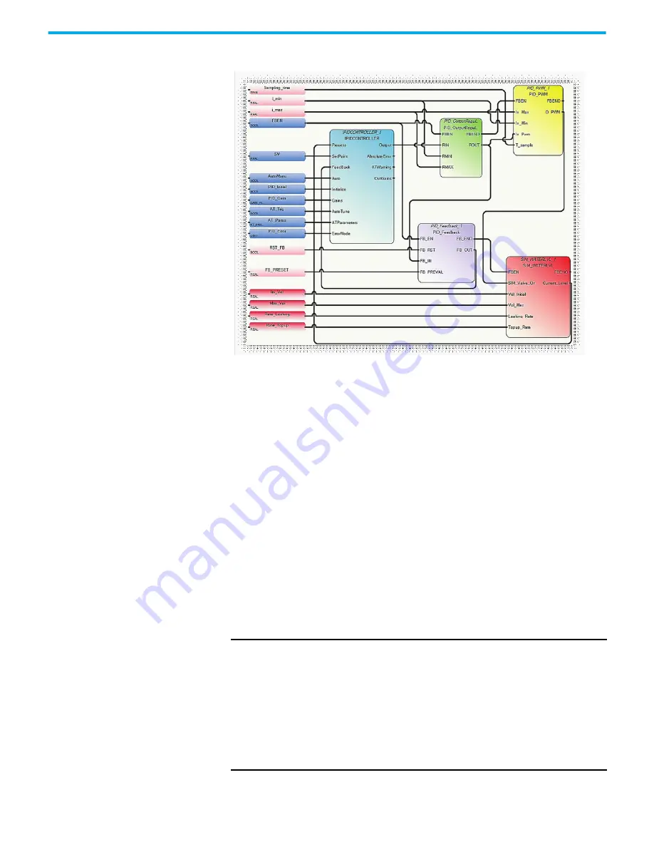
PID Code Sample
The illustration PID Code Sample shows sample code for controlling the PID application
example shown before. Developed using Function Block Diagrams, it consists of a pre-defined
function block, IPIDCONTROLLER, and four use-defined function blocks. These four are:
• PID_OutputRegulator
This user-defined function block regulates the output of IPIDCONTROLLER within a safe
range to ensure that there is no damage to the hardware used in the process.
IF RMIN
≤
RIN
≤
RMAX, then ROUT = RIN,
IF RIN < RMIN, then ROUT = RMIN,
IF RIN > RMAX, then ROUT = RMAX.
• PID_Feedback
This user defined function block acts as a multiplexer.
IF "FB_RST" is false, FB_OUT=FB_IN;
If "FB_RST" is true, then FB_OUT=FB_PREVAL.
• PID_PWM
This user defined function block provides a PWM function, converting a real value to a
time-related ON/OFF output.
• SIM_WATERLVL
This user defined function block simulates the process depicted in the application
example shown before.
IMPORTANT
User Program Scan Time is Important
The autotuning method needs to cause the output of the control loop to
oscillate. In order to identify the oscillation period, the IPID must be
called frequently enough to be able to sample the oscillation adequately.
The scan time of the user program must be less than half the oscillation
period. In essence the Shannon, or Nyquist-Shannon, or the sampling
theorem must be adhered to.
In addition, it is important that the function block is executed at a
relatively constant time interval. One can typically achieve this using STI
interrupt.