background image

59

vIdEO SETUP

Video Format

< >

Resolution to Display
Video Format

1080i

60Hz

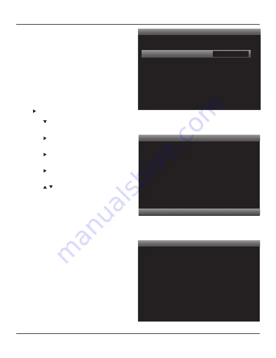
Diagram 65  

Setup Menu - Video Setup

Video Format

If video does not return after applying changes,
please wait 30 seconds and the previous settings
will be restored.

Press < to Return

Press > to Save

Diagram 66  

Video Format Screen

DVD 1

Analog Audio Input
Digital Audio Input
Video Input
Speaker Setup
Resolution
Input Audio Format
Listening Mode
Volume
Trigger Out

Audio 1

Optical 1

Component 1

3/2.1

1080i 60Hz

Dolby Digital
Dolby Digital

-20 dB

Main

Diagram 67  

Info Screen

cific connection (HDMI, component, S, composite) other 

than HDMI @ 480i. (HDMI does not output 480i.)

Any HDMI signal can be up-converted or down-converted 

to any resolution (1080p, 1080i, 720p, 480p) as an HDMI 

signal other than HDMI @ 480i. (HDMI does not output 

480i.) HDMI signals are not down-converted to analog 

signals (component, S, composite).

To change the Resolution to Display setting:

Note:

 If the OSD does not appear on the Video Display, 

try other Video Display inputs with connections to M80 

Monitor OUTs (component, S, composite) until the OSD 

appears. Add a component, S or composite video connec-

tion, if necessary, to access the OSD for setup.

1.

  With the OSD open, and Setup Menu selected, press 

. Source Setup will highlight in the Setup List.

2.

  Press   five times so Video Setup is highlighted in the 

Setup List. 

Diagram 62

3.

  Press   . The Video Setup Menu will appear. Video 

Format will be highlighted. 

Diagram 63

4.

  Press   . The Video Format screen will appear. Resolu-

tion to Display will be highlighted. 

Diagram 64

5.

  Press   . The Resolution to Display window will be-

come active. 

6.

  Press      to select the desired resolution. 

Diagram 

65

7.

  Press OK to select the setting. The  OSD and video 

output will turn OFF when selecting a new resolution. 

Allow up to 30 seconds for the M80 to try to set the 

selected resolution. There is some serious number 

crunching going on. The M80 needs to reconfigure 

its output and then sync with the video display, (and 

audio processing). This can take between 10 and 30 

seconds depending upon the resolution selected and 

the display. (Sometimes switching sources with differ-

ent input resolutions will take a few seconds to sync.)

8.

  If compatible with the video display, the picture will 

resume at the new resolution with the Video Format 

Screen open. 

Diagram 66 

Press 

>

 to Save the setting. 

Press 

<

 to return to the previous setting if the setting 

is undesirable.


9. 

If the M80 was not able to set the selected resolution, 

the video signal will be re-established at the previous 

Resolution to Display setting. Try another resolution 

until a compatible/desirable setting is selected.

10. 

To confirm resolution, press the Info button on the 

M80 Remote. The Info Screen will appear. 

Diagram 67 

Summary of Contents for M80

Page 1: ...Audio Systems M80 7 1 Channel Surround A V Receiver Installation User Guide ...

Page 2: ... has two blades with one wider than the other A grounding type plug has two blades and a third grounding prong The wide blade or the third prong are provided for your safety If the provided plug does not fit into your outlet consult an electrician for replacement of the obsolete outlet 10 Protect the power cord from being walked on or pinched particularly at plugs convenience receptacles and the p...

Page 3: ...ential installation This product generates uses and can radiate radio frequency energy and if not installed and used in accordance with the instructions may cause harmful interference to radio communications However there is no guarantee that interference will not occur in a particular installation If this product does cause harmful interference to radio or television reception which can be determ...

Page 4: ... Antenna 26 XM Satellite Radio Tuner 26 Audio Video 1 2 3 In Connections Default 28 Audio 5 In Out Connections Default 32 Audio 6 In Connections Default 34 Multi Input Connections 36 Pre Out 37 Trigger Out 37 IR IN OUT Connections 38 Video Display Connections 39 AC Outlets Connections 40 AC Power Cord 40 FRONT PANEL CONNECTIONS 41 Audio Video 8 Front Panel A V Connections 41 Headphones Connection ...

Page 5: ...st 61 Color 61 MPEG Noise Reduction 62 Cross Color Suppressor 62 Film Mode Detect 63 operating the m80 64 Install M80 Remote Batteries 64 Turning ON the M80 64 Selecting a Source 64 Volume 65 Mute 65 Tone Controls 65 Operating the Tuner 67 Selecting the Tuner 67 Tuning Manual 67 Tuning Direct Numeric 67 Presets 68 XM Tuner 69 Selecting the XM Tuner 69 XM Search Modes 69 All Channel Search 70 Categ...

Page 6: ... 2 Wiring 86 Speaker Wire Requirement 87 Video Cable Requirements 87 IR Control Wire Requirements 87 ZONE 2 SPEAKER CONNECTIONS 87 Speaker Connections 87 Zone 2 Subwoofer 87 ZONE 2 TV VIDEO DISPLAY CONNECTIONS 88 Composite Video 88 S Video 88 ZONE 2 IR CONTROL CONNECTIONS 88 Amplifier Setup 91 Zone 2 Controls 91 Power 91 Source 92 Volume 93 ZONE 2 REMOTE FEATURES 94 OPERATING ZONE 2 95 ON 95 OFF 9...

Page 7: ...7 notes ...

Page 8: ...nnels and up to 40 XM Preset Channels The M80 OSD On Screen Display will output an on screen graphic for AM FM frequency and Preset to the Main Room Video Display The OSD will also display metadata for channel preset artist and song for a connected XM Ready Tuner that can also be controlled by the M80 Remote The M80 features a dedicated iPod audio input and communication port When connected to the...

Page 9: ... IN OUT Loop 1 Composite Video Monitor Out 5 S Video Inputs 1 S Video IN OUT Loop 1 S Video Monitor Out 3 Component Video Inputs Y Pb Pr 1 Component Video Monitor Out 4 HDMI Inputs v1 3a 1 HDMI Monitor Out v1 3a Speaker Configurations Stereo 5 1 Surround 7 1 Surround 5 1 Surround 2nd Zone Stereo Control 2 IR Control Inputs 1 IR Control Output Sleep Timer 12VDC Configurable Trigger Output Front Pan...

Page 10: ... encoding of the content being played 4 BACK EXIT Press this button when the On Screen Display OSD is open to step backward in menu navigation or ultimately exit the OSD 5 SOURCE With the M80 power ON press this button repeatedly to select the desired source The source name or selected input will appear on the Front Panel Display to indicate the selected source 6 PHONES SETUP MIC Connects to a sta...

Page 11: ...dio mode Tuner information frequency preset tuned stereo Volume level briefly while volume is being set and for five seconds after XM and iPod metadata Mute and Sleep Timer The brightness can be set with the Dimmer button on the M80 Remote Control The Front Panel Display turns OFF when the M80 is in Standby 10 CURSOR After pressing the Main Menu button on the M80 Front Panel or Menu button on the ...

Page 12: ...tal audio device for recording and playback of digital audio content Note Only connect the Optical OR Coaxial Digital Audio Output of a digital audio device DO NOT connect both OUT Connect to the coaxial digital input of a digital audio recording device such as a media server or CD R RW to record digital audio IN Connect to the coaxial digital audio output of a CD DVD player MP3 player HDTV Tuner ...

Page 13: ...component connections and does not have HDMI connections All composite and S Video input is up converted for output on the Component Video Monitor OUT IN Connect to the Component Video OUT Jacks on appropriately featured audio video devices The component video inputs must be configured in the On Screen Display OSD Source Setup They can be associated with Sources 1 2 3 5 6 7 Multi Input and Source ...

Page 14: ... IR Flasher This connection also allows the M80 to be controlled via the M80 Remote when the M80 is hidden in an equipment closet or enclosed cabinet IR signals received at these inputs can also control any devices controlled via the IR OUT Jack Visit www proficientaudio com and select accessories for additional information on IR control products Zone 2 Connect either jack to the standard IR Flash...

Page 15: ...r audio signal M80 Source 4 is configured specifically for iPod iPod Dock 31 AUDIO VIDEO 2 3 RCA Jacks 1 S Video Jacks Connect to the left and right analog line level audio and composite video outputs of a DVD Player Satellite Receiver Cable Box or other audio video device default configuration Audio Video 2 is selected by repeatedly pressing the Source button on the M80 Front Panel or by pressing...

Page 16: ...an be renamed and optional digital audio inputs can be configured in the Source Setup under Source 5 Optional composite S or component video or HDMI inputs can also be configured for video input with Audio 5 Note Digital audio inputs coaxial optical HDMI are not down converted to analog line level audio and cannot be recorded Multi Input audio is not downmixed and cannot be recorded IN Connect to ...

Page 17: ...Surr Back Left and Surr Back Left Speaker five way binding posts on the M80 to the Main Room Surround Back Left and Surround Back Left Speaker Terminals Connect the Surr Right and Surr Right Speaker Terminals on the M80 to the Main Room Surround Back Right and Surround Back Right Speaker Terminals These connections are used for 7 1 Surround and 2 Zone configurations See section Multizone Configura...

Page 18: ...Modes are not available for all sources Available Listening Modes are determined by speaker configuration 5 1 vs 7 1 source con nections analog vs digital and the encoding or non encoding of the audio content being played 45 RESOLUTION Press this button to open or close the Video Format Resolution to Display screen Available resolutions Auto 480i 480p 720p 1080i 1080p Note Resolution to Display sh...

Page 19: ...uned frequency in the Tuner On Screen Display OSD PRESET With the AM FM or XM Tuner selected a press of this button will select the next programmed Tuner Preset That is if currently on Preset 4 a press of the Preset button will select Preset 5 After selecting the highest number programmed Preset the M80 will return to Preset 1 The selected Preset Number is indicated on the Front Panel Display to t...

Page 20: ... down The audio output level in dB decibels will be displayed on the Front Panel Display while either button is being pressed and for three seconds after a volume adjustment is made 63 iPOD M80 ON iPod Select With the M80 in Standby ON Standby button backlight red press this button to turn the M80 ON select the iPod Input Audio 4 and activate the iPod On Screen Display OSD With the M80 ON press th...

Page 21: ...installing the M80 it is critical that the fan openings and all chassis vents be kept clear to assure proper air flow Closed spaces such as equipment cabinets and racks can get hot with the heat generated by microprocessors and motors in vari ous devices Providing proper ventilation for good air flow will help keep the temperature down and protect not only the M80 but all system components and hel...

Page 22: ...turally occur behind the listener such as reflected sound off a back wall or a plane flying overhead from front to rear Low frequencies bass get sent to the Subwoofer A discrete Subwoofer channel enhances natural low frequen cy sounds in explosions jet engines the pounding of waves or wind and the music from the sound track 7 1 Surround Eight speaker configuration similar to 5 1 Surround but with ...

Page 23: ...ind the Ideal Listening Zone approximately 30 off axis from center essentially in line with the Front left right Speakers Subwoofer placement is somewhat less critical in that low frequency information is non directional Diagram 5 Placement of 7 1 Surround Speakers When placing speakers in a 7 1 configuration always try to maintain an equal distance from each speaker to the Ideal Listening Zone Th...

Page 24: ...iagram 7 shows a typical application for connecting speakers to the M80 in a 7 1 Surround configuration Connections for a 5 1 Surround configuration are as shown in Diagram 7 without the Surround Back Speakers Connections for a stereo configuration are as shown without the Surround or Back Surround Speakers The subwoofer connection is optional in a stereo configuration Note The M80 can safely driv...

Page 25: ...nected to the M80 Speaker Terminals Please refer to the subwoofer manufacturer s instructions for connection and operating options for varying subwoofer applications Note Some audio encoding provides a discrete LFE Low Frequency Effects Channel that is engineered as part of a surround audio mix Some Listening Modes will manufacture a subwoofer channel by separating low frequency content from the a...

Page 26: ... through the hole in the plastic end piece XM Satellite Radio Tuner This XM Ready connection requires an external XM Ready Satellite Radio Tuner The M80 does not have an on board XM Satellite Radio Tuner 1 Connect the XM Antenna to the XM Satellite Radio Tuner per the tuner manufacturer s instructions 2 Make any other necessary connections for proper operation of the XM Satellite Radio Tuner per t...

Page 27: ...ome source audio content may sound better as an analog audio signal so having the analog line level connections made provides additional options for critical listening users Option No HDMI The Option Diagrams show the connection options typically available for a given source These options include the coaxial and optical digital audio connections These connections provide more dynamic audio signals...

Page 28: ...his source so no additional configura tion is required with these connections 1 Using a stereo A V patch cable with gold ends con nect the L R line level audio OUT of the source to the L R Audio 1 IN on the M80 Connect the com posite video OUT of the DVD Player to the Video 1 Composite IN on the M80 2 Repeat Step 1 to connect additional A V devices to the Audio Video 2 3 Inputs using the Analog Au...

Page 29: ...1 a separate multichannel analog audio connection from the device to the M80 Multi Input is required to properly reproduce the DVD Audio or SA CD content played on that device See section Connections Multi Input Refer to the owners manual for any HDMI device to verify the HDMI version for that device On line updates may be available The M80 is HDMI v1 3a Digital Audio The digital audio connections...

Page 30: ...ation is required with these connections 1 Using a stereo A V patch cable with gold ends con nect the L R line level audio OUT of the A V Recorder to the Audio 1 L R IN on the M80 Connect the com posite video OUT of the A V Recorder to the Video 1 Composite IN on the M80 2 Using a stereo A V patch cable with gold ends con nect the L R Audio 1 OUT on the M80 to the appro priate L R line level audio...

Page 31: ...udio record playback device do not connect both The digital IN OUTs typically allow record playback of digital audio content and associated surround en coding Copyright protection can prevent some digital audio content from being recorded digitally so having the analog line level audio connections in place for backup is recommended to record the audio content as analog audio The M80 does not down ...

Page 32: ...atch cable with gold ends connect the L R analog line level audio OUT of the Audio Recorder to the L R Audio 5 IN on the M80 Note If the device is an audio video playback only device use any compatible unused video input See section Audio Video 1 2 3 Connections for additional information Be sure to select the ap propriate video input in Source Setup 2 Using a stereo RCA RCA patch cable with gold ...

Page 33: ...any unused digital coaxial or optical IN on the M80 Either coaxial or optical input can be used Be sure to configure the digital audio input used in Source Setup Note If the device is an audio video playback only device use any compatible unused video input See section Audio Video 1 2 3 Connections for additional information Be sure to select the appropriate video input in Source Setup 2 Using the...

Page 34: ...nections Option for information on optional connections These connections match the Source Setup input de fault settings for this source so no additional configura tion is required with these connections 1 Using a stereo RCA RCA patch cable with gold ends connect the L R analog line level audio OUT of the source to the L R Analog Audio 6 IN on the M80 Note If the device is an audio video playback ...

Page 35: ...tent from the source to the Zone 2 Speakers Zone 2 OUT or Zone 2 PRE OUT if used 1 Using either a digital coaxial or optical audio cable connect the appropriate digital audio OUT of the source to any un used digital coaxial or optical IN on the M80 Either coaxial or optical input can be used Be sure to configure the digital audio input used in Source Setup Note If the device is an audio video play...

Page 36: ... Audio 5 OUT Zone 2 OUT or Zone 2 PRE OUT L R line level audio jacks The Multi Input Front left right inputs can be used as a stereo source input but the Listening Modes will not be available The Multi Input connections shown in Diagram 19 match the Source Setup Analog Audio input default settings for this source so no additional configuration is required with these connections The Digital Audio V...

Page 37: ...BSR Surround Back Right and BSL Surround Back Left Out jacks on the M80 to the amplifier A proper 5 1 Cable will have color coded RCA plugs that match the color coding on the PRE OUT jacks 2 Do not connect the S W Out on the M80 to the amplifier unless the amp is going to power the subwoofer 3 Confirm proper connection of audio channels Improper connections will have an adverse effect on surround ...

Page 38: ...ram 22 shows an application where the M80 IR IN 1 is con nected to a Proficient IR Control System In this case all of the sources have compatible IR Control Inputs and are daisy chained for IR control without using IR Flashers M80 IR OUT Mono Mini to Mono Mini Cable Source A Rear Panel Source B Rear Panel Remote Control FLASHERS STATUS IN 5 24V DC IR RCVR 12V DC REGULATED FLASHERS 12V GND ST OUT I...

Page 39: ...rces with HDMI connections to the M80 with component S or composite video connections as available The M80 does not down convert HDMI Video to component S or composite video 1 Using a Component Video Cable with gold ends connect the M80 Component Monitor OUT to an appropriate Component Video Input on the Video Display as shown in Diagram 23 Change Resolution to Display to 1080i or lower if necessa...

Page 40: ...he power cord for a switched device to the AC Outlet on the M80 Rear Panel as shown in Diagram 24 2 Set the mechanical power switch on the switched device to the ON position AC Power Cord 1 After all connections have been made and confirmed con nect the female IEC plug into the AC Input on the M80 Rear Panel and then plug the AC power cord into an unswitched 110V AC outlet Diagram 25 2 The ON Stan...

Page 41: ...cable with gold ends con nect the L R line level audio OUT on the source to the Front L R Audio INs on the M80 2 Connect the composite video OUT on the source to the Front Video IN on the M80 3 Connect the S Video OUT on the source to the Front S Video IN on the M80 if available Option S Video will provide improved picture quality over the com posite video signal Be sure to select the S Video Inpu...

Page 42: ...nce Tone Controls DSP Options Listening Mode Mode Center Gain Analog Bypass 0 2 Diagram 28 OSD Default Screen and Navigation Controls USING THE OSD After confirming all connections as described in the previous sections turn the M80 all Sources and the Video Display ON 1 Press the Menu button on the M80 Front Panel or M80 Remote The OSD default screen Diagram 28 should appear on the Video Display I...

Page 43: ...tton on the M80 Front Panel or Remote to navigate to the Setup Menu Screen Diagram 29 If any problems were encountered opening the OSD no video on the Video Display follow the instructions in sec tion Video Setup Source Setup The Source Setup is where the input connections are config ured sources are named and the 12 V Trigger Out is config ured 1 With the OSD open and Setup Menu selected press th...

Page 44: ... blank space and standard punctuation marks Diagram 34 1 Press to move the highlight bar to the Name line 2 Press The Source Name Window will become active The cursor will move to the space for the first character 3 Alternately press the and buttons to enter the characters for the source name Blu ray used for example Diagram 34 Note The M80 will automatically center the name in the Setup List when...

Page 45: ...a couple times to get a feel for which ones are louder and softer when compared to the others 2 Press to move the highlight bar to the Gain line Note The Gain line will turn off for any source with Analog Audio set to Off no analog audio input as signed 3 Press The Gain Window will become active 4 Press to select the appropriate level if needed 0dB used for example 5 When finished press so the Gai...

Page 46: ...the highlight bar to the Trigger Out line 2 Press The Trigger Out Window will become active 3 Press to select the appropriate setting 4 When finished press so the Trigger Out Window is no longer active and to save the setting Source Setup Normal View Source Name Analog Audio Gain Digital Audio Video Trigger Out 1 BLU RAY Audio 1 0 dB HDMI 1 HDMI 1 Yes Diagram 38 Video Input Source Setup Normal Vie...

Page 47: ...d Dock when an iPod is docked and the M80 is ON Diagram 41 1 Press The Auto Connect Window will become ac tive 2 Press to select Yes No Yes used for example 3 When finished press so the Auto Connect Window is no longer active The setting will save automatically Menu Timeout This setting will determine how long the iPod Menu will remain on screen after navigating to the iPod Menu from the Now Playi...

Page 48: ...tests the speaker setup and room conditions to cre ate perfect balance for a natural sound environment Please review the sections in SmartEQ and Manual Speaker Setup for additional information on these critical settings Important Note The M80 determines which Listening Modes are available for the selected source based upon the number of speakers 5 1 or 7 1 configuration the input analog or digi ta...

Page 49: ...mmended Disconnected closed air headphones can be used or earplugs can be purchased in better drug stores musical instrument stores or building supply outlets where heavy tools are sold 1 Press The SmartEQ Connect Microphone screen will appear 7 1 speaker configuration will be high lighted by default Diagram 45 2 Connect the measurement microphone as shown in Diagram 46 The speakers will be turned...

Page 50: ...ll automatically adjust the output delay to each speaker until all speakers have the same response time This will compensate for less than ideal speaker placement if all speakers are not equal distance from the Ideal Listening Zone This will assure sound from all speakers is heard at the same time for focus creating a natural sounding audio environment Checking Speakers Level and Size Starting wit...

Page 51: ... for variations in room shape such as an alcove which can trap sound or soft surfaces of upholstered chairs that can dull high frequencies SmartEQ Procedure Completed When Smart EQ has finished the Procedure Complete screen will appear Diagram 50 1 Press once to return to the Speaker Setup Menu Diagram 44 2 Press again to return to the Setup Menu Dia gram 43 To Exit the OSD 1 Press the Menu button...

Page 52: ...r These settings are determined by the number of speakers used and the design of the Front Center Surround and Back speakers Selecting Large is appropriate when full range speakers with good bass extension are used for Front Center Surround or Back or if a Subwoofer is not going to be used Selecting Large will send all bass information for that group Front Center Sur round Back to those speakers a...

Page 53: ...nmental sounds and music tracks for movies and TV program that are appropriately encoded for surround sound Only adjust the Sur round and Back speaker levels if they are unusually loud or soft when playing relative to the Front and Center speakers Range 12dB The values shown in Diagram 52 are for example only 1 With the Speaker Setup Menu open Diagram 44 press to move the highlight bar to the Spea...

Page 54: ...s The Speaker Distance screen will appear Unit of Measure will be highlighted by default Diagram 53 2 Press The Unit of Measure Window will become active 3 Press to select feet or meters Once values are entered the M80 will automatically convert feet to meters and meters to feet if the setting is changed 4 When finished press so the Unit of Measure Win dow is no longer active and to save the setti...

Page 55: ...o set Main Back or Zone 2 6 When finished press so the Back Amp Window is no longer active and to save the setting 7 If continuing in Setup Menu press to return to the Setup Menu and proceed to the next section 8 To exit the OSD press Menu Trigger Setup These settings determine when the 12V Trigger Out on the M80 Rear Panel is activated and deactivated The Trigger Out can be used to turn external ...

Page 56: ...2 6 When finished press so the Trigger Out Window is no longer active and to save the setting Delay This setting will have the Trigger Out turn ON 0 15 sec onds after the mode selected on the Trigger Out line is turned ON The Trigger Out will turn OFF instantly when the selected mode Main Source Zone 2 is turned OFF Range 0 15 seconds 1 From the Trigger Out line press so the Delay line is highligh...

Page 57: ...rs the M80 s internal Tuner an XM Tuner iPod or any stereo audio source VHS tapes with Dolby Stereo or Dolby Surround encoding will not trigger Listening Modes automatically but some Dolby PLII IIx Movie Music and DTS NEO 6 Cinema Music modes can be applied manually or set as preferences to enhance the encoded soundtrack The Listening Mode Setup default preferences are set to None This allows the ...

Page 58: ... If continuing in Setup Menu press to return to the Setup Menu and proceed to the next section 11 To exit the OSD press Menu Video Setup These settings will configure the Monitor Outputs from the M80 to the Main Room Video Display Video Format sets the M80 Resolution to Display and Picture Setup sets the bright ness contrast color and filters Video Format The Resolution to Display factory default ...

Page 59: ... the Setup List 2 Press five times so Video Setup is highlighted in the Setup List Diagram 62 3 Press The Video Setup Menu will appear Video Format will be highlighted Diagram 63 4 Press The Video Format screen will appear Resolu tion to Display will be highlighted Diagram 64 5 Press The Resolution to Display window will be come active 6 Press to select the desired resolution Diagram 65 7 Press OK...

Page 60: ...Mode Detect are special filters that enhance picture quality in specific applications The Picture Quality factory default is set to Normal In most cases the settings for Brightness Contrast and Color should not be changed and desired adjustments to the video signal appearance should be made using the adjustments on the Video Display These settings can be changed if changing the settings produces a...

Page 61: ...gs will reduce black level Set so pure black objects are black not gray It can sometimes be help ful to turn the color all the way off when making this adjustment 4 To continue in Video Modes press so the Bright ness Window is no longer active and to save the set ting 5 Continue to Contrast or press Menu to exit the OSD Contrast This setting will determine the white level in the picture The white ...

Page 62: ...so the Color Window is no longer active and to save the setting 5 Continue to MPEG or press Menu to exit the OSD MPEG Noise Reduction This setting will determine the level of MPEG Noise Reduc tion MNR MNR is used to reduce blocking artifacts and mosquito noise that result from MPEG compression on TV signals This type of picture degradation is most notice able around titles with a contrasted backgr...

Page 63: ...g 5 Continue to Film Mode or press Menu to exit the OSD Film Mode Detect This setting will turn the Film Mode Detect ON OFF Film Mode Detection also known as 3 2 Pulldown Detect removes motion artifacts from 24 frame per second film content that has been converted to 30 frame per second video Options ON OFF 1 Press so Film Mode Detect is highlighted in the Picture Setup List 2 Press The Film Mode ...

Page 64: ...shown in Diagram 78 The M80 will turn ON to the last source selected Using the M80 Remote press one of the Source 1 8 Tuner or iPod buttons as shown in Diagram 78 for the desired source The M80 will turn ON to that source The ON Standby Backlight will turn blue and the Front Panel Display will turn ON The M80 will go through a start up se quence of 5 seconds The M80 will not respond to commands du...

Page 65: ...am 81 M80 Remote Tone Controls M80 Remote M80 Front Panel Display Tone Controls Tone Controls M80 Remote The Tone Controls can be changed from the M80 Remote without using the OSD This option is useful if the M80 is being used in an audio only mode and the Video Display is turned off or if activating the OSD will interfere with the Video being played Tone Control changes from the remote will be di...

Page 66: ...isplay is not directly visible 1 Press the Main Menu Button on the M80 Front Panel or Menu button on the M80 Remote The OSD will ap pear on the Video Display 2 Press two times so Tone Controls is highlighted in the OSD Menu Diagram 82 3 Press The Tone Defeat line be highlighted 4 If Tone Defeat is ON press The Tone Defeat win dow become active 5 Press to set Tone Defeat to OFF 6 Press then the Tre...

Page 67: ...splayed d If the channel is a Preset the Preset Number will be displayed Band 1 Repeatedly press the Tuner or Band button on the M80 Remote to select AM FM or XM Tuning Manual 1 With AM or FM selected press the Cursor buttons on the M80 Front Panel or M80 Remote or the TUNE but tons on the M80 Remote to decrease or increase the tuner frequency by one increment If the tuned frequency is also a Pres...

Page 68: ...y Diagram 86 3 Press the Memory button again the tuned channel will be stored as a Preset 4 If all Presets for a given band have been used press the OK button on the M80 Remote so PRESET appears in the Front Panel Display 5 Quickly press the Memory button P and P01 will alternately flash on the Front Panel Display 6 Quickly enter the Preset number 1 30 to be replaced The previously stored channel ...

Page 69: ... When XM is selected the last tuned XM Channel and Channel Name will appear in the M80 Front Panel Dis play If the Video Display is ON the XM OSD will appear automatically The XM Category Neighborhood Channel Name Channel Number Artist and Song Title and will be displayed in the OSD Diagram 88 If there is a problem with the antenna CHECK ANTENNA will appear in the Front Panel Display and OSD as sh...

Page 70: ...nnel has been selected Diagram 88 Tuning XM Preset Channels Manual 1 With the XM Tuner set to All Channel Search press the Cursor buttons on the M80 Front Panel or M80 Remote or the PRESET buttons on the M80 Remote to scroll up down XM Preset Channels buttons on the Front Panel or Remote and the Tune buttons on the Remote In Category Search the Numeric buttons will directly tune all XM Channels re...

Page 71: ...is selected The previously stored channel will be deleted and the currently tuned channel will be stored Preset X Saved will appear on the Front Panel Display Or 5 If all XM Presets have been used select the XM Channel to be stored as a Preset then press the Memory button Quickly enter the Preset Number 1 40 to be replaced The previously stored channel will be deleted and the currently tuned chann...

Page 72: ...lay and iPod NOT DOCKED will ap pear in the OSD as shown in Diagram 96 iPod Menu Navigation 1 With the Main Room Video Display ON and if not already on screen press the iPod Menu button on the M80 Re mote to activate the iPod OSD Menu Note iPod Menu and metadata are not displayed on the Zone 2 Video Display 2 Press buttons to highlight a menu item Repeatedly press the buttons to scroll to items no...

Page 73: ... press The Main Menu item will change to Shuffle Off Navigate the iPod OSD to make another selec tion Repeat The Repeat function will play a selected song or playlist con tinually until stopped or another selection is made 1 To repeat a song select a song from a playlist With Repeat Off highlighted in the Main Menu press The Main Menu item will change to Repeat One and the iPod will continually pl...

Page 74: ...elect the Source to be recorded by selecting the Source from the M80 Front Panel or Remote The Source to be recorded will be displayed in the Front Panel Display 2 With the source to be recorded connected with the default connections analog line level audio and composite video and with the appropriate Analog Audio and Composite Video Inputs selected in Source Setup press record on the record play ...

Page 75: ...up Many Blu ray Players have on board decoding capability for Dolby or DTS encoded audio content If so the player may decode the audio content and output it as a PCM bitstream When this occurs the M80 Front Panel Display will indicate Multi ch PCM This indicates that the Blu ray Player has decoded the audio content before outputting it to the M80 over the HDMI connection The Blu ray Player Setup c...

Page 76: ... OSD and Front Panel Display 5 Press so the Mode Window is no longer active The Listening Mode will save automatically Dolby Digital Dynamic Range Control 6 With Dolby Stereo Dolby Digital or Dolby Digital EX selected in Step 5 above press The Dynamic Range Control line will be highlighted 7 Press to select the desired setting See section Listening Modes Dolby Setup for additional information Dolb...

Page 77: ...selection only Note The Listening Mode screen will show the settings for the last source selected with the OSD OFF 2 Open the OSD and with Setup Menu selected press Source Setup will highlight in the Setup List 3 Press four times so Listening Mode Setup is highlighted in the Setup List Diagram 101 4 Press The Listening Mode Setup Menu will appear Listening Mode will be highlighted Diagram 102 5 Pr...

Page 78: ...options preferences for Dolby en coded stereo and surround audio input signals Available modes will vary 2 Channel This setting will have any Dolby Ste reo encoded content output in the selected mode Typical 5 1 configuration modes DVS Reference DVS Wide Dolby PLII Movie Dolby PLII Music Typical 7 1 configuration modes Stereo Downmix DVS Refer ence DVS Wide Dolby PLIIx Movie Dolby PLIIx Music Dolb...

Page 79: ...hannel Stereo Diagram 108 To set Preferences 1 With the OSD OFF select a source other than Tuner or iPod Listening Modes are configured by source except Tuner and iPod which have manual selection only Note The Listening Mode screen will show the settings for the last source selected with the OSD OFF 2 Open the OSD and with Setup Menu selected press Source Setup will highlight in the Setup List 3 P...

Page 80: ...ering the volume late night listening will cause some of the subtle nu ances of the surround mix to drop to levels that adversely affect the surround effect Adjusting the dynamic range helps maintain the relation of these variables and pre serves the integrity of the surround mix even at lower volume Adjusting dynamic range can also be helpful for protecting speakers from particularly high transie...

Page 81: ... As a result the surround mix will appear to move toward the front and sound a little more dry Setting a lower number will decrease the center channel level and typically reduce the focus of the vocals As a result the surround mix will appear to move toward the rear and sound more open and ambient Diagram 115 To adjust Dolby and DTS Setups 1 With the OSD open and Setup Menu selected press Source S...

Page 82: ...l send special effects signals to the surround channels for a more full and dramatic impact Music mode provides three additional user controls Center Width Panorama and Dimension for customizing the surround mix Available in 7 1 configuration for any stereo or 5 1 audio source Displayed as PLIIx Movie Music Game Dolby Pro Logic II Movie Music Dolby Pro Logic II can covert any quality stereo audio ...

Page 83: ...splayed as DTS NEO 6 Music Stereo Downmix Stereo Downmix is a 2 channel output of DTS multichannel encoded content This allows some DTS mul tichannel content to be played trough two speakers in a Producer Mix without loosing any of the voice soundtrack or ambient sound characteristics when the M80 is setup in a 7 1 configuration Displayed as DTS Stereo OTHER MODES Multi Channel PCM Multi Channel P...

Page 84: ... Diagram 116 3 Press The Lip Sync Delay line will be highlighted Diagram 117 4 Press The Lip Sync Delay Window become active Diagram 118 5 Press to set Delay Adjust until the audio and video on the video display are in sync Voice audio and lip movement video are good indicators 6 Press so the Lip Sync Delay Window is no longer active The setting will save automatically 10 Press to return to the OS...

Page 85: ... the selected source as configured in Source Setup Speaker Setup Indicates the channel configuration of the audio input signal for the selected source In Diagram 120 the first number 3 indicates the Front Speakers left center right The second number 2 indicates the Sur round Speakers surround left right The 1 indicates an LFE Subwoofer channel This indicates a 5 1 audio signal As another example 2...

Page 86: ...an external amplifier for Zone 2 audio the Surround Back speakers must be configured for Zone 2 in the OSD Menu under Setup Menu Amplifier Setup Zone 2 Wiring The Zone 2 application described in this section requires that one pair of speaker wires be run from the M80 location to each speaker in Zone 2 An appropriate shielded video cable RG6 for composite video or S Video cable for S Video will als...

Page 87: ...with S Video plugs on both ends Line Level Audio Cable Requirements 1 Pull 1 run of 22AWG 2 pair shielded cable up to 50 feet from the M80 location to the Zone 2 Video Display location Leave extra length 24 inches on both ends to work with when making connections Terminate with RCA plugs on both ends Note It is not necessary to connect line level audio to the Video Display if amplified audio is be...

Page 88: ...R control system can be con nected to IR IN 1 or IR IN 2 on the M80 Rear Panel This al lows the M80 to be controlled from Zone 2 using the Zone 2 Remote Control Diagram 124 shows an application where IR IN 2 is con nected to a Proficient IR Control System These connec tions allow remote control of Zone 2 ON OFF source selection volume mute and Tuner Preset selection The M80 Zone 2 Remote controls ...

Page 89: ...l Optical Audio OUT Proficient C850 Ceiling Speakers Audio Sense Switch Diagram 125 Zone 2 Single Room High Power Audio System ZONE 2 AS A SINGLE ROOM WITH HIGH POWER AMPLIFIER Diagram 125 shows the M80 Zone 2 PRE OUT connected to the line level in on a Proficient M2 125 Watts per channel stereo am plifier This configuration provides high power audio for a large room or patio area with volume cont...

Page 90: ...Y PLAYER CD PLAYER PROFICIENT M80 2 ZONE A V SURROUND RECEIVER M8 BLU RAY PLAYER DIGITAL AUDIO OUT OPTICAL COAXIAL L R LINE LEVEL OUT V S VIDEO OUT COMPONENT VIDEO OUT Y Pb Pr Line Level Audio Composite Video OUT HDMI OUT Line Level Audio OUT Digital Optical Audio OUT Normal Connections Diagram 126 Zone 2 Multiroom Audio System ZONE 2 AS MULTIPLE ROOMS WITH 8 CHANNEL POWER AMPLIFIER Diagram 126 sh...

Page 91: ...have external speakers in Zone 2 The M80 Zone 2 PRE OUT or Zone 2 OUT can be connected to the line level audio inputs on the Zone 2 Video Display to have Zone 2 audio output through the Zone 2 Video Display speakers Using the Zone 2 PRE OUT will allow volume to be controlled using the M80 Zone 2 Remote Using the Zone 2 OUT will allow volume to be controlled using the Video Display remote If using ...

Page 92: ...xit the OSD press Menu Source The Zone 2 Source can be selected from the OSD This is convenient for setting a whole house music mode from the Main Room if Zone 2 has been set up as a multiroom zone 1 With the OSD open and Zone 2 Controls selected press Power will highlight in the Setup List 2 Press so Source is highlighted in the Setup List 4 Press The Source Window will become active 5 Press to s...

Page 93: ...tion 1 With the OSD open and Zone 2 Controls selected press Power will highlight in the Setup List 2 Press twice so Volume is highlighted in the Setup List 3 Press The Volume Window will become active 4 Press to set Fixed to set a fixed level Diagram 134 5 When finished press so the Volume Window is no longer active The setting will save automatically 6 Press so Level is highlighted in the Setup L...

Page 94: ...one 2 ON press this button to select the previous M80 Source 4 PRESET With the AM FM or XM Tuner selected press this button to select the previous programmed Tuner Preset That is if currently on Preset 4 a press of the Preset button will select Preset 3 If Preset 1 is currently selected the M80 will return to the highest number programmed Preset Tuner Preset is not displayed for Zone 2 PRESET With...

Page 95: ...FF Press the Power button on the Zone 2 Remote When Zone 2 is turned OFF the M80 Front Panel Display will indicate Z2 OFF for about 10 seconds in the lower line The Main Room Source will continue to be displayed in the upper line Diagram 138 Volume With Zone 2 ON press the Volume buttons on the Zone 2 Remote to adjust Zone 2 Speaker or Zone PRE OUT audio output If Zone OUT is used that is a fixed ...

Page 96: ... if used m Refer to sections Listening Modes Setup and Operating The M80 Listening Modes Video No Video Signal on TV or Video Display a Confirm source video connections to M80 b Confirm Video Input Settings in OSD Source Setup b Confirm HDMI Component S Composite Video Monitor OUT from M80 Monitor OUT to TV Video Display HDMI Component S Composite Video IN c Confirm proper Input is selected on the...

Page 97: ...in Room for Surround Mode processing c Confirm Zone PRE OUT or OUT connections to an external amplifier d Confirm OSD Zone 2 Controls Setup e Confirm Zone 2 speaker connections f Confirm Zone 2 volume is turned up and un muted g Confirm Zone 2 source is selected turned on and playing No Video a Confirm Zone 2 source composite and or S Video connections b Confirm Zone 2 composite and or S Video con...

Page 98: ... into 8 Ohms 130 Watts 20Hz to 20kHz Rated Continuous Power Output Channel 2 channels driven into 8 Ohms 100 Watts 20Hz to 20kHz THD at rated power 0 05 Rated Continuous Power Output Channel 2 channels driven into 4 Ohms 160 Watts 0 1 1kHz Damping Factor 100 all channels Input Sensitivity For rated power max VC 250 mV Line IN Input Impedance Source Inputs 47 K Ohms Line IN Input Overload Source In...

Page 99: ...ivity 20 dB Quieting 1000kHz loop antenna 500 mV m Selectivity S N 20dB 10 kHz 30 dB S N Ratio 400 Hz 10 mV m Input 1000 kHz 30 Mod 45 dB THD 400 Hz 10 mV m Input 1000 kHz 30 Mod 0 8 Selectivity 10 kHz 25dB Image Rejection 1400 kHz 34 dB Control Sections IR Control IR 1 2 IN 5 V p p Active High with Carrier IR OUT 5 V p p Active High Stripped Carrier 4V with 270 Ohms Loading Trigger OUT Trigger Ou...

Page 100: ...C Center Width 3 Dimension 0 Panorama Off DTS SETUP DEFAULT SETTINGS NEO 6 MUSIC Center Gain 0 2 appendix M80 DEFAULT SETTINGS The following Charts provide reference to M80 Factory Settings The M80 is a highly evolved Audio Video Surround Receiver with features that can satisfy even the most discriminating user With so many options it is possible to change some of the settings to a point where the...

Page 101: ...ROOM NOTE VIDEO UP DOWN CONVERSION ONLY APPLIES FOR SOURCE INPUTS TO MAIN ROOM MONITOR OUTPUTS VIDEO 1 OUT AND ZONE 2 COMPOSITE AND S VIDEO OUTS ARE PASS THROUGHS FOR SAME SIGNAL LEVEL ONLY HDMI Component Video S Video Com posite OUTPUT 1080p 1080i 720p 480p 480i 1080i 720p 480p 480i 480i 480i INPUT HDMI 1080p X X X X 1080i X X X X 720p X X X X 480p X X X X 480i Component 1080i X X X X X X X X X X...

Page 102: ...lti In VIDEO INPUTS Video 1 IN Video 1 OUT Video 2 Video 3 Video 4 Video Front S Video 1 IN S Video 1 OUT S Video 2 S Video 3 S Video 4 S Video Front Component 1 Component 2 Component 3 HDMI 1 HDMI 2 HDMI 3 HDMI 4 appendix M80 WORKSHEETS Use the following Worksheets to document connections and settings to assist in installation and setup Keep these Worksheets in a safe convenient location for futu...

Page 103: ...er Levels Distance Delay MAIN ROOM VIDEO DISPLAY CONNECTIONS Model Number Composite Video Monitor Out S Video Monitor Out Component Video Monitor Out HDMI Monitor Out ZONE 2 CONNECTIONS AUDIO External Amp Model Number Zone 2 PRE OUT variable Zone 2 OUT fixed Zone 2 Speakers Model Number VIDEO Zone 2 Video Display Model Number Zone 2 Composite Video Out Zone 2 S Video Out ...

Page 104: ... Custom Option Brightness Contrast Color MPEG Noise Reduction Cross Color Suppressor Film Mode Detect OTHER SETTINGS LIP SYNC DELAY TONE CONTROLS Treble Bass ZONE 2 CONTROLS Power Source Volume Level AMPLIFIER SETUP BACK AMP TRIGGER OUT TRIGGER DELAY LISTENING MODE PREFERENCES SOURCE 1 SOURCE 2 SOURCE 3 IPOD SOURCE 5 SOURCE 6 MULTI IN FRONT SOURCE NAME Model Number LISTENING MODE Dolby Digital 2 C...

Page 105: ...Cinema is a trademark of Genesis Microchip Inc HD DVD HD DVD is a trademark of the DVD Format Logo Licensing Corporation DVD FLLC HDMI HDMI the HDMI logo and High Definition Multimedia interface are trademarks or registered trademarks of HDMI Licensing LLC iPod iPod iTunes and Apple are trademarks of Apple Inc registered in the U S and other countries Macrovision This product incorporates copyrigh...

Page 106: ...USIONS This Warranty does not include service or parts to repair damage caused by accident disaster misuse abuse negligence inad equate packing or shipping procedures commercial use voltage inputs in excess of the rated maximum of the unit or service repair or modification of the product by unauthorized dealers This Warranty also excludes normal cosmetic deterioration caused by environmental condi...

Page 107: ...107 notes ...

Page 108: ...1300 74080 rev1 Audio Systems 940 Columbia Avenue Riverside CA 92507 877 888 9004 Fax 951 750 6304 proficientaudio com 2009 Proficient Audio Systems ...

Reviews: