ChartScan User’s Manual
ChartScan - Unit Startup and ChartView Tutorial 1-3
3. Check and Install Hardware
Depending on your order, your ChartScan unit may not require all the steps under this heading. If a
step does not apply to your unit, simply go on to the next one.
a) Verify Voltage Setting
Based on your order, your ChartScan system was set at the voltage indicated on the sticker (located on
the rear of the unit, near the power switch). Verify that the voltage value indicated on the sticker
matches the voltage of your intended AC power supply. If you need to change the voltage selection for
any reason, refer to Chapter 3,
Power Aspects, Changing the Voltage Setting.
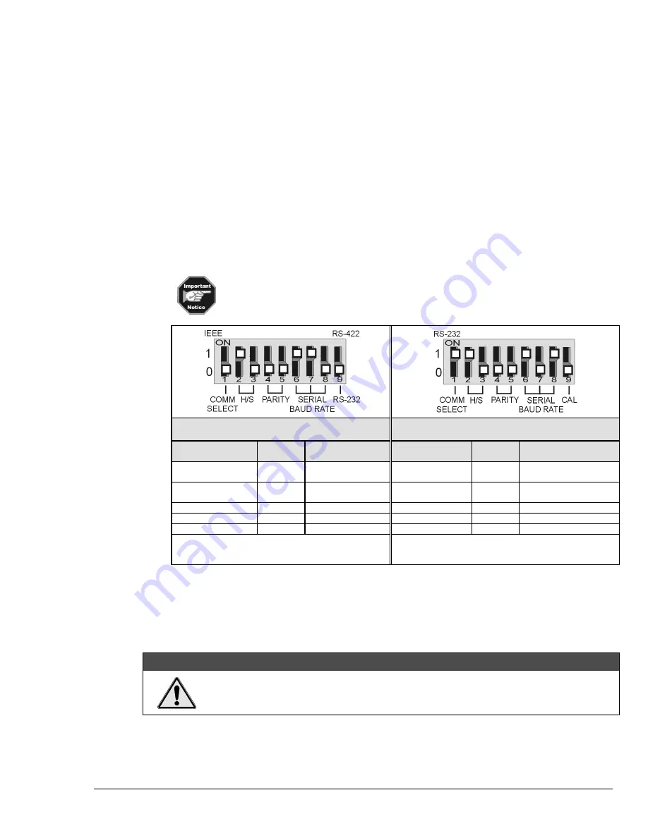
b) Verify DIP Switch Setting
The DIP switch is located on the lower right corner of ChartScan’s rear panel. Default settings are
indicated in the following figures and table. Refer to Chapter 3 if you desire to change the RS-232
parameters from their default values, or if you wish to use the IEEE 488 interface option. For ethernet
use of ChartScan, make sure the unit is configured for RS-232 serial communications, then refer to the
Net232 User’s Guide
(p/n 1037-0901).
Early production
ChartScan units do not have a Calibration Enable/Disable
Pushbutton. If you have an
early production
unit, refer to the right-hand DIP switch
illustration.
DIP Switch Default Settings
Dip Switch Default Settings
(Early Production Units Only)
Selection
Micro-
Switch #
Setting
Selection
Micro-
Switch #
Setting
COMM SELECT
1
0 – Serial
Communication
COMM SELECT
1
1- RS-232
HANDSHAKE
(H/S)
2,3
1,0 - Hardware
Handshake
HANDSHAKE
(H/S)
2,3
1,0 - Hardware
Handshake
PARITY
4,5
0,0 - No Parity
PARITY
4,5
0,0 - No Parity
BAUD RATE
6,7,8
1,1,0 – 19200 Baud
BAUD RATE
1
6,7,8
1,0,1 - 9600 Baud
RS-232 or RS-422
9
0 – RS-232
CALIBRATION
9
0 - Disabled
1
It is recommended that you do not exceed 9600 Baud
unless you have firmware version 1.3 or greater. The
firmware version can be read in
ChartView’s
title bar.
c) Install Signal Conditioning Card(s)
Signal conditioning cards are pre-installed per customer order. However, if you need to install a signal
conditioning card, or CSN/Relay card, perform the following steps. Repeat the steps for additional
cards, and for placing cards into the optional CSN/Exp expansion chassis, if applicable.
CAUTION
CAUTION
CAUTION
CAUTION
Ensure ChartScan is powered down and not connected to any power source prior to
installing or removing a card. Failure to do so could cause equipment damage.
Summary of Contents for OMB-CHARTSCAN 1400
Page 1: ...August 2002 OMB CHARTSCAN 1400 Portable Data Recorder p n OMB 483 0901 Rev 3 1...
Page 6: ...iv ChartScan User s Manual...
Page 24: ...ChartScan User s Manual...
Page 32: ...2 8 General Information ChartScan User s Manual Notes...
Page 56: ...3 24 ChartScan User s Manual Notes...
Page 124: ...6 20 Calibration ChartScan User s Manual...
Page 126: ...A ii ChartScan User s Manual...
Page 136: ...API Commands Appendix A A 10 ChartScan User s Manual Notes...
Page 176: ...API Commands Appendix A A 50 ChartScan User s Manual...
Page 230: ...Appendix C Registers Data Formats Queries ChartScan User s Manual C 13...
Page 237: ...Registers Data Formats Queries Appendix C C 20 ChartScan User s Manual Notes...
Page 257: ...E 2 ChartScan User s Manual Notes...
Page 265: ...ASCII Code Summary Appendix F F 8 ChartScan User s Manual Notes...
Page 269: ...Abbreviations Appendix H H 2 ChartScan User s Manual Notes...
Page 271: ...ChartScan User s Manual...


