3-10
ChartScan User’s Manual
IEEE 488 Interface Configuration (Option)
The IEEE 488 interface option is intended for digital communication with IEEE 488 compliant computer platforms,
as well as IEEE 488 compliant
platform-independent
configurations. Data is transmitted parallel, as opposed to
serial. The IEEE 488 option allows for up to 15 devices to be connected to one bus; with a total bus length of up to
20 meters. Allowable cable distance between devices is up to 2 meters. Message transactions are hardware
handshaked.
This section describes the configuration for ChartScan that will be commanded through the IEEE 488 bus when
using ChartScan’s IEEE 488 interface option. To use this option, an IEEE 488 interface card must be installed in
ChartScan’s interface slot and the rear panel DIP switch must be properly configured for IEEE 488. Note that all
IEEE 488 bus devices, including ChartScan (when the IEEE 488 interface option is used) must have an IEEE 488
bus address. The micro-switches 4 through 8 (on the rear panel DIP switch) can be used to assign an IEEE 488
address. Switch setting are discussed in,
IEEE 488 Configuration
, presented shortly.
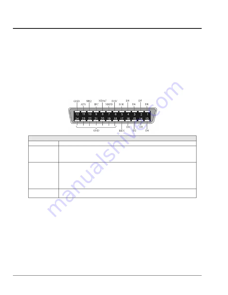
IEEE 488 Pinout
IEEE 488 Pinout
Data Lines
Eight lines (D1 through D8) used to transfer data and commands between devices on the bus.
Handshake Lines
DAV
NDAC
NRFD
Used to handshake the transfer of information across the data lines.
DAV: Data Valid
NDAC: Not Data Accepted
NRFD: Not Ready for Data
Bus Management
Lines
ATN
IFC
REN
SRQ
EOI
Five bus management lines are used to control bus activities.
ATN: Attention
IFC: Interface Clear
REN: Remote Enable
SRQ: Service Request
EOI: End or Identity
Ground Lines
Eight ground lines used as follows: one for shield, one for general signal ground, and six logic
ground lines (one for each of the following: DAV, NDAC, NRFD, ATN, IFC, and SRQ).
Specifications
Compliance Note:
•
The IEEE 488 interface card is compliant with IEEE 488.2 specifications.
Installation Category:
•
CE:
Category 1
Implementation:
•
SH1, AH1, T6, TE4, L4, LE4, SR1, PP0, RL0, DC1, DT1, C0, E1
Programmable Parameters:
•
Alarm set points, thermocouple type, temperature units, trigger level, pre-trigger and post-trigger scan interval,
trigger mode, SRQ mask, scan count, pre-trigger count, digital input, digital output, real time settings, data
output format, and terminators.
Data Transfer Speed:
•
Up to 1Mbyte/s
Connector:
•
Standard IEEE 488 connector with metric studs
Summary of Contents for OMB-CHARTSCAN 1400
Page 1: ...August 2002 OMB CHARTSCAN 1400 Portable Data Recorder p n OMB 483 0901 Rev 3 1...
Page 6: ...iv ChartScan User s Manual...
Page 24: ...ChartScan User s Manual...
Page 32: ...2 8 General Information ChartScan User s Manual Notes...
Page 56: ...3 24 ChartScan User s Manual Notes...
Page 124: ...6 20 Calibration ChartScan User s Manual...
Page 126: ...A ii ChartScan User s Manual...
Page 136: ...API Commands Appendix A A 10 ChartScan User s Manual Notes...
Page 176: ...API Commands Appendix A A 50 ChartScan User s Manual...
Page 230: ...Appendix C Registers Data Formats Queries ChartScan User s Manual C 13...
Page 237: ...Registers Data Formats Queries Appendix C C 20 ChartScan User s Manual Notes...
Page 257: ...E 2 ChartScan User s Manual Notes...
Page 265: ...ASCII Code Summary Appendix F F 8 ChartScan User s Manual Notes...
Page 269: ...Abbreviations Appendix H H 2 ChartScan User s Manual Notes...
Page 271: ...ChartScan User s Manual...


