PV8344F4E013
16
2.2.
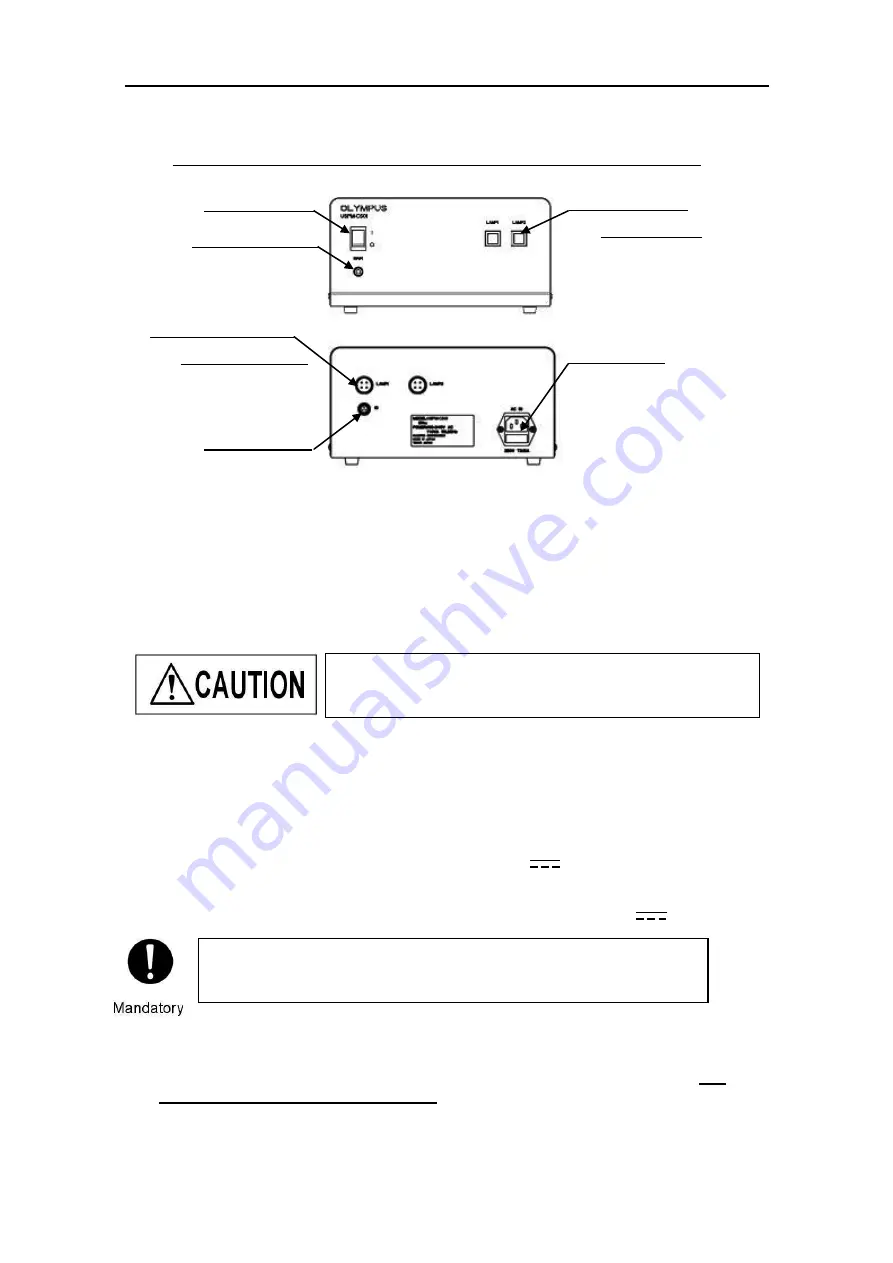
The names and functions of the items on the controller supply unit
The functions and operating methods are shown below:
1. Power
switch
Turn on or off the power of the controller supply unit.
2. Power
indicator
Light on when power is on and off when power is off.
3. Lamp 1 switch / Lamp 2 switch
Supplies power to the lamp house or switches the power destination. Turning on a
switch supplies power through the corresponding connector (Lamp 1 or Lamp 2
connector) to illuminate the halogen lamp.
4. Lamp 1 connector / Lamp 2 connector
Each connector supplies power to the corresponding lamp house.
Connect a LAMP cable to each connector. (DC 12V )
5. IO
connector
Supplies control voltage to the unit. Connect an IO cable. (DC 12V )
6. Power
inlet
Connect the power cord here to supply power to the controller supply unit. The
component is equipped with a fuse. For details on replacing the fuse, refer to
3.4
Installation and replacement of fuses
.
Front view of the controller supply unit
Rear view of the controller supply unit
2. Power indicator
4. Lamp 1 connector
Lamp 2 connector
5. IO connector
6. Power inlet
3. Lamp 1 switch
Lamp 2 switch
1. Power switch
Lamp 2 switch and connector are used with an optional unit
(Transmittance measurement set, 45-degree measurement set).
Always use the supplied cable.
With any other cables, there is a risk of malfunction due to internal or external
noise. The supplied cables may not be used for any other devices.


