background image

PV9576-F4E006 4 


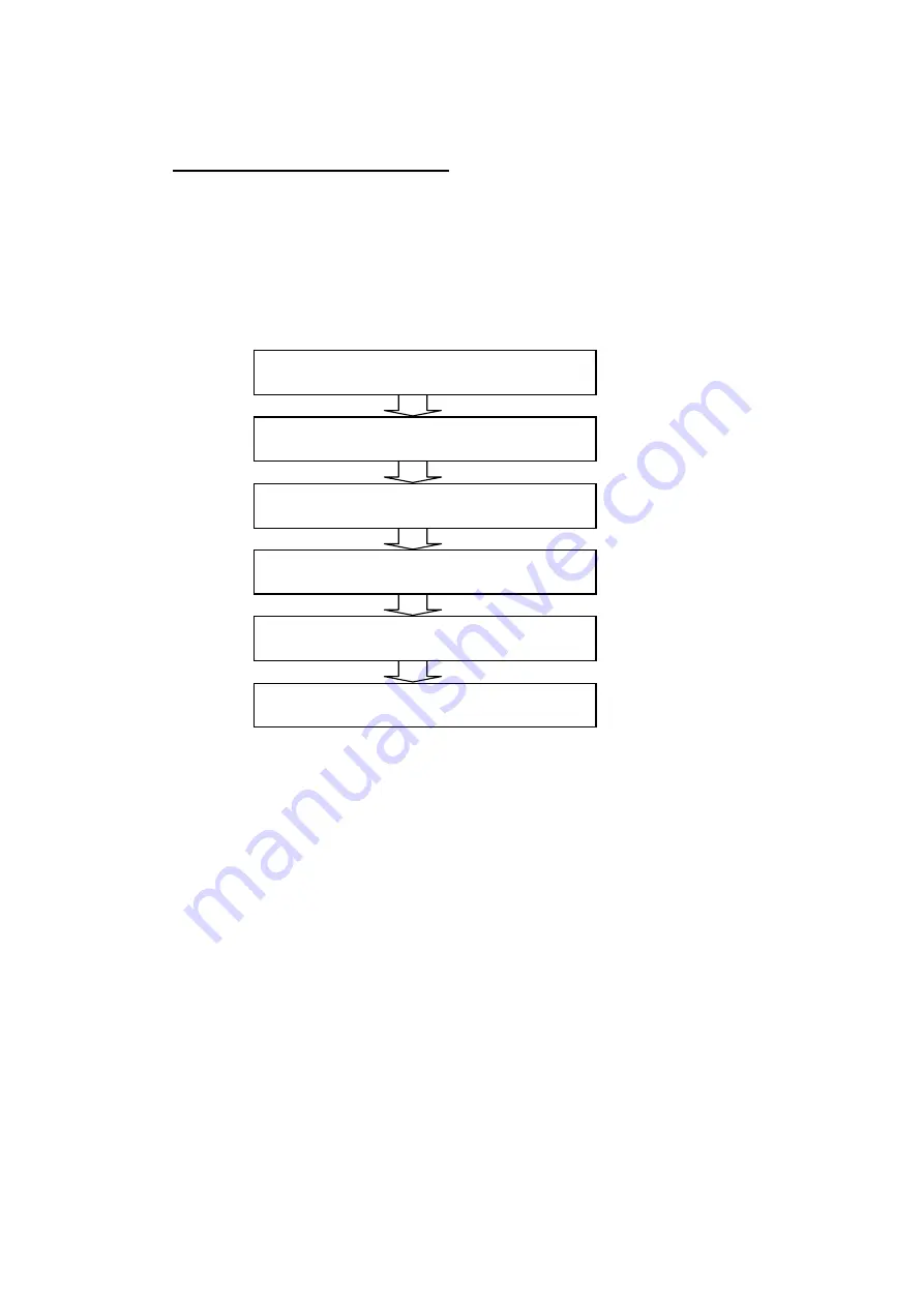
1.4.  Installation and uninstallation flow 

"6. Verifying the driver installation result" must be performed after the installation of each driver 
is completed. Thus, follow the procedures below for a new installation. For other installation and 
uninstallation cases, perform them by referring to the relevant chapter as necessary. When you 
install the software application, execute a wavelength calibration by following the instruction 
manual of the relevant product after the installation is completed. 


„

 Flow of a new installation 


7. Installing software 

2. Installing the communication port driver 

3. Installing the FOCUS camera driver 

4. Installing the CT camera driver 

5. Installing the protection key driver 

6. Verifying the driver installation result 

Summary of Contents for USPM-RU-W Series

Page 1: ...ter To use this product safely and satisfactorily benefit from doing so please take the time to carefully read this Operation Manual before using the product Keep this manual handy when using the prod...

Page 2: ...f Parts and their Specifications 14 3 Installation and Connection 19 4 How to Use 26 5 Precautions for Storage 41 6 Troubleshooting 44 7 Compliance with Regulations 46 Appendix 47 Principles of measur...

Page 3: ...epartment Regular inspection is recommended in order to achieve safe use and reduce downtime About the reference sample The reference data once a year is recommended to be updated because 45reference...

Page 4: ...or starts to peel contact your supplier or our sales department for a replacement Symbols Description Don not touch with your hand There is a risk of burns Indicates any unspecified danger Follow the...

Page 5: ...ox The box has the following symbols Indicates this side up Indicates the box should be protected from rain Indicates the items inside are fragile and the box should be handled with care Indicates the...

Page 6: ...sales representative where you purchased the unit or the sales department at Olympus NEVER repair or modify the unit NEVER disassemble or modify the unit except to replace consumables Otherwise there...

Page 7: ...o not place the unit in a location that is exposed to direct sunlight or in a location that is subject to extreme variations in temperature such as near heating equipment or thermal equipment Do not p...

Page 8: ...e vents Install the unit at least 10 cm away from a wall Since the lamp house gets hot when the lamp is illuminated place the unit at a point at least 10 cm away from any walls Operating the unit near...

Page 9: ...cord Do not operate the unit with wet hands Operating the unit or removing inserting the power plug with wet hands may cause electrical shock Ground the unit securely Connect the earth terminal of a t...

Page 10: ...s hot just after the light is turned off Wait until the lamp cools before replacing it Otherwise there is a risk of burns Pay attention when adjusting focus In adjusting focus pay close attention to t...

Page 11: ...al during the warranty period 2 We do not warrant any failure due to other causes ex peripheral devices or the environment of the installation site 3 Regardless of the warranty period there will be a...

Page 12: ...dly welcome any questions Contact the support division given in the attachment Although we went to great effort to confirm the accuracy of the contents of this document if you feel that certain points...

Page 13: ...surement of thin plates The product is able to measure plates of thickness of 1 mm 0 15 mm with an optional x40 objective lens Reflectivity measurement of Part around lens The reflectivity measurement...

Page 14: ...photometer USPM W B Operation Manual 2 Spectral Analysis Software USPM SA Operation Manual 3 Spectral Analysis Software USPM SA Installation Instructions 4 Main unit 5 controller supply unit 6 Lamp ho...

Page 15: ...1 Reference 11 Wavelength calibration sample 1 Reference of wavelength calibration 12 USB cables 2 1 5 m 13 Lamp cable 1 1 5 m 14 IO cable 1 1 5 m 15 Application software CD ROM 1 Including drivers 1...

Page 16: ...supply unit via the lamp cable 2 Lamp house Accommodates a halogen lamp For details refer to 3 Installation and Connection 3 Photometric head Contains the optical system for spectrophotometry 4 IO con...

Page 17: ...ocus adjuster Moves the photometric head and an objective lens in the vertical direction The load adjuster is available for adjusting the load on the motion of focus 9 Shift stage The coarse tuning kn...

Page 18: ...able to each connector DC 12V 5 IO connector Supplies control voltage to the unit Connect an IO cable DC 12V 6 Power inlet Connect the power cord here to supply power to the controller supply unit The...

Page 19: ...of sample 1 0mm 0 5mm 0 2mm Shift stage Size of mounting 200 W u 200 D mm Load 3 kg Operating range XY 40 mm Z 125 mm Rotation stage OPTIONAL Sample that can be loaded Diameter 5 60mm surface of flan...

Page 20: ...PV8344F4E013 18 Temperature 15 C 30 C Humidity 15 60 RH non condensing Voltage fluctuation 10 Contamination 2 IEC60664 1 Installation Category Overvoltage Category II IEC60664 1...

Page 21: ...nstalling or transferring it Damages to optical parts or effects on adjustment may result causing failure or incorrectness Keep the photometric head at the lowest position during installation or trans...

Page 22: ...er of objective lenses you want to attach Then insert the objective lenses into the revolver Be sure to insert them fully Revolver Object lens If the temperature of the unit is greatly different from...

Page 23: ...e of the main unit Confirm the threaded holes and the lamp house are properly aligned Tighten the two fixing knobs to secure the lamp house Lamp house Halogen lamp Levers Lamp connector Lamp socket Fi...

Page 24: ...tightly 2 Remove the four screws on the back with the cross shaped tip screwdriver and remove the upper cover 3 Remove two screws on the top side of the rack with the cross shaped tip screwdriver and...

Page 25: ...as spring with a slotted screwdriver 12 Remove the replacement jig of the gas spring 13 Fix the covers with the screws 14 Turn the load adjuster counterclockwise to loosen it Load adjuster Four screws...

Page 26: ...lts into the fixing hole How to remove the work plate 1 Remove the four bolts M3 u 5 2 Remove the work plate installed on the upper surface of the stage If the optional tilt stage is attached remove t...

Page 27: ...d 5 Protection key Any USB port on the computer 3 USB cable 3 USB cable 4 Power cord USB 1 USB 2 IO LAMP 1 IO 1 Lamp cable LAMP 2 IO cable PC 5 Protection key Take care not to apply excessive force in...

Page 28: ...sition of the BK7 reference sample o Refer to4 6 Setting the BK7 reference sample Setting the sample to be measured 7 Adjust the sampling interval o Refer to 4 8 Adjusting the sampling interval 8 Obta...

Page 29: ...g 4 11 Spectroscopy Refer to 4 12 Analysis of film thickness o When measuring color difference after conducting 4 11 Spectroscopy Refer to 4 13 Calculation of color difference 13 Check the result o Re...

Page 30: ...g interval 6 Obtain the background value o Refer to 4 9 Obtaining the background value 7 Obtain the reference value o Refer to 4 10 Obtaining the reference value 8 Put the sample to be measured o Refe...

Page 31: ...l USPM OBL10 USPM OBL20 USPM OBL40 Magnification 10x 20x 40x NA 0 12 0 24 0 24 Range Spot dia 70 m 35 m 17 5 m Distance 14 3 mm 4 2 mm 2 2 mm curvature radius of sample 5mm 1mm 1mm Thickness of sample...

Page 32: ...Choose Setup Work on the File menu The work setup window opens 2 Configure the reference When using BK7 reference sample When using the optional high reflectivity reference sample 1 Click V and selec...

Page 33: ...re on the black area to switch between FOCUS and CT in the LIVE window You may obtain the same effect through choosing Live on the menu A FOCUS window appears when the time the software opens 1 Adjust...

Page 34: ...ed in the following figure to adjust the gain so that a circle is displayed Looking at CT window use the shift adjuster to move the sample toward the vertical direction against the optical axis Align...

Page 35: ...reference sample use the former sample to adjust the sampling interval Hint An error may occur due to the input value If you encounter an error check the message to modify the input value If the input...

Page 36: ...captured After that the shutter operates again and a warning alarm sounds as the process finishes As the data is saved an asterisk appears at the left of REFERENCE in the operation panel 4 11 Spectro...

Page 37: ...a set item Feature of each mode of analysis Set item of each mode of analysis Peak valley method PV Fourier transform method FFT Curve fit method FIT Feature of each mode of analysis A complex settin...

Page 38: ...For detail on each method refer to 6 3 Layer setting in the UPSM SA Software Operation Manual LAYER Design parameter of the layer to be analyzed There is no need to set up if METHOD is PV and UNIT is...

Page 39: ...it into the desired position 3 Adjust tilt of the BK7 reference sample Use the strength knob to adjust the strength properly Then looking at the FOCUS window use the angle knob to turn the BK7 refere...

Page 40: ...le to the desired for the measurement Use the scale 4 17 Adjusting the position of the sample to be measured when using the rotation stage 1 Looking at the beam from the objective lens use the shift a...

Page 41: ...displays the result of spectroscopic reflectance measurement The vertical axis indicates the reflectance and the horizontal axis the wavelength 2 TEXT window The TEXT window shows the values of the me...

Page 42: ...dow 6 LUMINANCE TEXT window The spectroscopic quantity values of the lights of background reference and measurement are displayed The interval of display is configurable in the graph setting window 7...

Page 43: ...the lens and then wipe it softly with a sheet of lens cleaning tissue or washed gauze Wipe off any fingerprints or oils with a sheet of lens cleaning tissue dampened with a little absolute alcohol Whe...

Page 44: ...2 How to calibrate wavelength The following section describes how to calibrate using the supplied calibration sample Calibration sample Setup of the work configuration file Refer to 4 5 Setup of the...

Page 45: ...ield As the value increases the measurement data shifts to a shorter wavelength in 1 nm increments Comparing the graph of reflectance generated from the measurement with the reflectance graph of the c...

Page 46: ...t 1 Check the strength of the load adjuster 2 Check for deterioration of the gas spring If the photometric head suddenly drops from its own weight when the focus lock is released there is the possibil...

Page 47: ...Wavelength offset to conduct a offset Display of wavelength in LUMINANCE window is incorrect 1 Turn off the controller supply unit and reboot the computer Display of wavelength in GRAPH window is inco...

Page 48: ...andby electricity and about 25 W of active power while active power often increases to 50 W depending on the peripherals and applications in use 7 3 About KC For Korean Customers h G G O G PG G G Oh P...

Page 49: ...ral reflectance of the reference The reference samples provided as an accessory with the product are composed of S BSL7 glass made by OHARA GmbH Precautions for safe use of the lighting device lamp ho...

Page 50: ...spection Inspection checklist 1 Eight years have elapsed since purchase or the total time of lamp use has exceeded 20 000 hours 2 Sometimes lamp does not illuminate even when you turn on the main swit...

Page 51: ...shown in Table 1 and or 2 The connector must be associated with any one of the certification marks in Table 1 If no cords certified by any of the certification organizations in Table 1 are available...

Page 52: ...10 30 N V KEMA KEMA KUER HAR 10 30 30 SEMKO AB Svenska Elektriska Materielkontrollanstalter SEMKO HAR 10 10 50 sterreichischer Verband f r Elektrotechnik VK VK HAR 30 10 50 Danmarks Elektriske Materie...

Page 53: ...reserved No part of this document in whole or in part may be copied or distributed without the permission of Olympus Corporation The company names and product names referred to in this document may b...

Page 54: ...for purchasing our spectral analysis software In order to use this software safely and to maximize the benefit from doing so be sure to read this instruction manual completely before use Please also k...

Page 55: ...irmation of Packaged Products 6 2 Installation and Wiring 7 3 Usage 8 4 Main Window 13 5 File Menu 17 6 Settings 23 7 Windows 44 8 Others 53 9 File Configuration and Format 54 10 Error Display 58 11 I...

Page 56: ...an error to occur Actively erase unnecessary data files Regarding how to erase data files see the OS manual Never delete and rename any folder prepared in the hard disk of the computer during deliver...

Page 57: ...properly thoroughly understand the contents of symbol marks and terms Symbol denoting prohibition prohibited actions Symbol denoting obligation mandatory actions Symbol denoting caution Indicates that...

Page 58: ...F4E005 5 Do not turn off hardware power during software start Doing so may result in improper operation Failure to follow the precaution below may result in injury or material damage to peripheral pr...

Page 59: ...completely received and check whether products are missing or damaged Contact the retailer or our branch office immediately if products are missing or if you have any questions regarding products CD R...

Page 60: ...tion according to the Installation procedure in the attached sheet Contact our business personnel if you have any questions 2 2 Wiring Insert a protection key into any USB port of your computer Wire t...

Page 61: ...and terminate the software Then turn off the power to all hardware 3 2 Measurement of spectral measured values spectral reflection factors and spectral transmission factors Various operation buttons...

Page 62: ...ss the OK button to complete the adjustment of the sampling time Executing background measurement Press the BACKGROUND1 button to execute background measurement for acquiring the spectral light intens...

Page 63: ...s of the saveing format see the 5 1 File menu A chromaticity diagram and its related numeric value are displayed on the DIAGRAM window The type of the chromaticity diagram can be changed on the GRAPH...

Page 64: ...o the sample to be analyzed for film thickness For details of the setting see the 6 3 Layer setting Analyzing the film thickness Press the ANALYZE button and execute film thickness analysis Sets the r...

Page 65: ...the 7 8 THICKNESS window and 7 9 THICKNESS INFO window A film thickness analysis method and its result are displayed For the contents of the display see the 7 8 THICKNESS window The state of film thic...

Page 66: ...menu Each file menu has submenus respectively For the details of each submenu please read each file menu item Menu Description File Several file operations Measure Several measurements and sampling a...

Page 67: ...analysis validated when measurements and film thickness analysis can be stopped SMPLNG ADJST Adjusts the sampling time automatically this operation is the same as that when pressing the F5 key of the...

Page 68: ...can be specified on another window Wavelength 1 wavelength Displays the selected wavelength value R T Refractive index Displays the spectral measured values of the selected wavelength value 4 3 Status...

Page 69: ...RAM Displays the chromaticity diagram GRAPH Displays the spectral measured values using a graph LIVE Displays the FOCUS and CT images LUMINANCE Displays the spectral light intensity using a graph LUMI...

Page 70: ...the Save As dialog box The saving format and its corresponding File type are as follows For CSV and DAT formats however Detail of data is not saved CSV files csv CSV format DAT files dat DAT format CS...

Page 71: ...as required These are printed in the header of the printed file In Data No select the spectral measured value data to be printed In Selected the currently selected spectral measured value data is prin...

Page 72: ...the operation panel Usage of this function is described in the section below 5 2 1 Sampling adjustment Sampling adjust is a function for automatically adjusting the sampling time The sampling time is...

Page 73: ...the OK button 5 3 Analyze menu The Analysze menu is constituted by the submenus below Menu Description Thickness Analyzes the film thickness Color difference Displays a color difference measurement w...

Page 74: ...s a LAYER setting window Graph Displays a GRAPH setting window System Displays a SYSTEM setting window Dispersion editor Displays a DISPERSION setting window 5 5 LIVE menu The LIVE menu is substituted...

Page 75: ...5 6 Help menu The Help menu is constituted by the submenus below Menu Description Instruction manual name Opens the instruction manual About Displays an information window About Firm Displays a firm i...

Page 76: ...escription TARGET Select the equipment to be connected For a near infrared micro spectrophotometer USPM RU W set this to USPM RU W COM CTLR Select the connection ID number of an internal arithmetic un...

Page 77: ...tus display of the operation panel The sampling time adjusted by Adjust sampling varies depending on this item Usually set this to 80 The setting range is an integer value of 0 to 100 FOCUS XY RANGE S...

Page 78: ...this to Disable FOCUS SIZE Sets the index during the automatic adjustment of a FOCUS window usually set this to 1000 The setting range is an integer value of 100 to 5000 FOCUS EXP Sets the exposure t...

Page 79: ...see the 6 2 1 Reference setting Sampling time Sets the sampling time exposure time the sampling time must be set so that the acquired spectral light intensity does not exceed the maximum value of the...

Page 80: ...ptability decision for details of the setting see the 6 2 2 Standard setting 6 2 1 Reference setting Menu Description Dispersion setting tab Select the type of a dispersion setting value to set the th...

Page 81: ...ing tab however this does not apply when FIXED or FILE is selected Calculating the spectral measured value data For this software a spectral reflection factor and transmission factor that are spectral...

Page 82: ...actor transmission factor are used to set the theoretical reflection factor transmission factor of a reference Four methods are provided in all 1 Setting the refractive index using the dispersion form...

Page 83: ...calculation expression can be set by creating a dispersion setting file on a DISPERSION editing window For details of dispersion settings see the 6 5 Dispersion setting 3 Setting the reflection facto...

Page 84: ...imit reflection factor values can be set to a maximum of 20 wavelengths Values of more than 0 must be entered to Lower and Upper Therefore when you want to set only Lower for example only Lower is ena...

Page 85: ...imum value in a reflection factor click the check box when enabling the set standard value Valley nm Sets the upper and lower limit wavelength values of a minimum value in a reflection factor click th...

Page 86: ...e of substrate Sets the refractive index of a substrate when using this item set it to Enable and then set the data filename used as the refractive index of a substrate A spectral measured value data...

Page 87: ...ractive index on a LAYER setting window according to the table below As the result of film thickness analysis the calculated value varies depending on each setting state Use this function to obtain a...

Page 88: ...layer setting when obtaining physical film thickness As in a peak valley method however this method cannot be used when two or more peaks and valleys do not exist in the analysis range 3 Curve fit me...

Page 89: ...alysis method is FIT When you enable FIX enter the thickness of the layer because the thickness of the selected layer is not treated for film thickness analysis When you disable FIX enter the thicknes...

Page 90: ...e a dispersion setting file using dispersion editing when changing values Specify the filename of the refractive index data in the File field when you select FILE Enter a refractive index using numeri...

Page 91: ...window The type of chromaticity diagram set here is displayed just after a value is measured L a b scale Select a display scale when the chromaticity diagram displayed on a DIAGRAM window is an L a b...

Page 92: ...a GRAPH window the horizontal axis is automatically adjusted when enabling AUTO and the horizontal gridline is automatically adjusted when enabling AUTO of gridline But according to the size of GRAPH...

Page 93: ...PV8959 F4E005 40 appears A dispersion setting file cf can be created and changed on the DISPERSION setting window...

Page 94: ...is a Schott dispersion formula and Cauchy is a Cauchy dispersion formula A dispersion formula is calculated using a calculation expression set in USER when you select USER C1 C6 Sets the coefficient...

Page 95: ...s used as the CSV file created in the format below Save Saves the created dispersion setting file Replace This saves the created dispersion setting file However a standard dispersion setting file cann...

Page 96: ...rrent dispersion setting file A refractive index ind format or reflection factor rf format can be selected as an output format Assign the name to be displayed and select it from the file type on a SAV...

Page 97: ...rescribed on each window SAVE You can select SAVE by clicking the right button The current data value and image are saved The format in which a data value is saved in is CSV format A format for saving...

Page 98: ...the selected data number s chroma Y Displays the measurement result of the selected data number s tri stimulus value Y x Displays the chromaticity coordinate x position of the selected data number s...

Page 99: ...ame of each color in a data graph a NAME input window appears when you click the mouse Data name and Data contents can be changed on the window Data graph This is the result data of spectral measured...

Page 100: ...when it is a CT camera image Center of gravity coordinates Displays the center of gravity coordinate position this item is displayed in red when the center of gravity coordinate position is out of th...

Page 101: ...nd blue respectively The pink graph indicates the lower limit value of the spectral light intensity set on a SYSTEM setting window The red graph indicates the maximum value of the spectral light inten...

Page 102: ...n a data graph a NAME input window appears when you click the mouse The data name can be changed on the window Data value This is the result data of the spectral measured values SAVE SAVE can be selec...

Page 103: ...an analysis method and the ND nd D nm field displays the analyzed optical film thickness physical film thickness The items below display the detected peak and valley wavelengths At that time the refr...

Page 104: ...of the film thickness analysis displayed on this window varies depending on the setting state of method on a LAYER setting window It is separately described below 7 9 1 Peak valley method PV Analysis...

Page 105: ...ss analysis It can be checked Film thickness is not also properly analyzed if the detection point is not properly displayed in the peak position 7 9 3 Curve fit method FIT Analysis data and theoretica...

Page 106: ...arguments and setting values during entry The parameter arguments and their corresponding setting values are shown in the table below The extensions of the setting values can be omitted Various setti...

Page 107: ...ting file layout Setting file for window arrangement Reference wavelength dispersion data file rf File for loading reflection factor Wavelength dispersion data file ind File for loading refractive ind...

Page 108: ...nt value of Data2 wavelength 1048 measurement value of Data10 wavelength 1048 1049 measurement value of Data1 wavelength 1049 measurement value of Data2 wavelength 1049 measurement value of Data10 wav...

Page 109: ...w True 2 CIE1931 False 10 CIE1964 L Data1 L Data2 L Data3 L a Data1 a Data2 a Data3 a b Data1 b Data2 b Data3 b x Data1 x Data2 x Data3 x y Data1 y Data2 y Data3 y HUE Data1 hue angle Data2 hue angle...

Page 110: ...dentification tag in steps of 1 nm The format below is used when using polarization USPM SA v1 00 REFERENCEFILE Identification tag of reference file Random polarized reflection factor data of 380 nm P...

Page 111: ...oftware Failed to load substrate file The file set to a substrate s refractive index is not proper or may be damaged Set a normal file Failed to load reference file The file set to the theoretical spe...

Page 112: ...curve fit method FIT of film thickness analysis Increase the quantity for enabling FIX Too dark Set manually Sampling adjustment cannot be used because the sampling time is long Set the time manually...

Page 113: ...tting the sampling time Press the Sampling adjustment button for automatic setting For details see the sampling adjustment item Or open the WORK setting window and set the Sampling time field manually...

Page 114: ...n password txt in C Program Files USPM SA conf folder is a password Open password txt and change the character string in the first line Recovering lost measured data A data file is saved in C Program...

Page 115: ...curacy of the contents of this document if you discover any unclear point or any mistakes omissions please contact the Service Department of Olympus Corporation as shown in the attached sheet For the...

Page 116: ...rve the regulations below Article 1 Intellectual property rights The right of this software belongs to Olympus This software is protected by the laws and treaties regarding other intellectual property...

Page 117: ...his software Olympus guarantees that substantial and physical defects that significantly disturb the operation or functions of this software do not exist in the media in which this software is recorde...

Page 118: ...ude the loss of lost profits business interruption the loss of business information or other pecuniary losses but not restricted to such resulting from use or the lack of serviceability of third party...

Page 119: ...PV8959 F4E005 66 The company and product names described in this manual may be trademarks or registered trademarks of their respective proprietors...

Page 120: ...u for purchasing our spectroscopic analysis software In order to use this software safely and to maximize the benefit from doing so be sure to read this instruction manual completely before use Please...

Page 121: ...ing the CT Camera Driver 13 5 Installing the Protection Key Driver 21 6 Verifying the Driver Installation Result 24 7 Installing Software 28 8 Uninstalling the Communication Port Driver 29 9 Uninstall...

Page 122: ...mation on computers with configurations that have been checked please contact our sales department Windows10 1 CPU Intel CPU 2 0 GHz or better PC AT compatible machine 2 Chipset Made by Intel Corporat...

Page 123: ...form them by referring to the relevant chapter as necessary When you install the software application execute a wavelength calibration by following the instruction manual of the relevant product after...

Page 124: ...n the CD ROM to execute it 3 If a warning screen is displayed at this time click the Continue button A warning related to the user account control may be displayed depending on the settings of the com...

Page 125: ...lace the CD ROM into the CD ROM drive 2 Double click MCM320 Setup_x64_win10 exe in the CD ROM to execute it A warning related to the user account control may be displayed depending on the settings of...

Page 126: ...to proceed SN 6K45356 REVISON A0 1 Place the CD ROM into the CD ROM drive 2 Double click MCM4303 Setup exe in the CD ROM to execute it A warning related to the user account control may be displayed d...

Page 127: ...6L40431 REVISON A1 1 Place the CD ROM into the CD ROM drive 2 Double click WIN7 MCM320 Setup exe in the CD ROM to execute it A warning related to the user account control may be displayed depending o...

Page 128: ...PV9576 F4E006 9 4 In the following screen click the Next button to proceed 5 In the following screen click the Next button to proceed...

Page 129: ...owing screen click the Next button to start the installation 7 When the following screen is displayed click the Finish button to proceed 8 Finally when the following screen is displayed click the OK b...

Page 130: ...e it A warning related to the user account control may be displayed depending on the settings of the computer used Click the Yes button to proceed with the installation 3 In the first screen click the...

Page 131: ...owing screen click the Next button to start the installation 7 When the following screen is displayed click the Finish button to proceed 8 Finally when the following screen is displayed click the OK b...

Page 132: ...CD ROM into the CD ROM drive 2 Double click Micron dpinst exe in the CD ROM to execute it A warning related to the user account control may be displayed depending on the settings of the computer used...

Page 133: ...exe in the CD ROM to execute it A warning related to the user account control may be displayed depending on the settings of the computer used Click the Yes button to proceed with the installation 3 n...

Page 134: ...F4E006 15 5 In the following screen select the 3 USB and click the Next button to proceed 6 In the following screen click the Next button to proceed 7 In the following screen click the Next button to...

Page 135: ...tton to proceed 9 In the following screen remove the Install a desktop shortcut to Install a quick launch shortcut to and Show quickstart HTML checkbox and click the Next button to proceed 10 In the l...

Page 136: ...used Click the Continue button to proceed with the installation 3 Copy both WIN7 Micron Mv46Cap_I sys and WIN7 Micron Mv46Raw_I sys to the C Windows system32 drivers folder 4 Copy the micron Mv46Prp_I...

Page 137: ...F4E006 18 4 In the following screen click the Next button to proceed 5 In the following screen select the 3 USB and click the Next button to proceed 6 In the following screen click the Next button to...

Page 138: ...xt button to proceed 8 In the following screen click the Install button to proceed 9 In the following screen remove the Install a desktop shortcut to Install a quick launch shortcut to and Show quicks...

Page 139: ...PV9576 F4E006 20 10 In the last screen click the Finish button to complete the installation...

Page 140: ...te it 3 If a warning screen is displayed click the Continue button A warning related to the user account control may be displayed depending on the settings of the computer used Click the Yes button to...

Page 141: ...ute it 3 If a warning screen is displayed click the Continue button A warning related to the user account control may be displayed depending on the settings of the computer used Click the Yes button t...

Page 142: ...PV9576 F4E006 23 6 In the following screen click the Next button to proceed 7 In the last screen click the Finish button to complete the installation...

Page 143: ...he installation results executed in Chapter 2 through to Chapter 5 First refer to the instruction manual of the product used then wire the computer and the product and then turn on the power 1 Open th...

Page 144: ...nd 4 First verify the communication port installation status Select Ports COM LPT and check that Silicon Labs CP210x USB to UART Bridge COM is displayed Note that the number at the position marked wit...

Page 145: ...eam Device is displayed Then select Universal Serial Bus controllers and check that MCM320 Image Acquisition Controller is displayed SN 6K45356 REVISON A0 Select Imaging devices and check that MCM4303...

Page 146: ...ect Universal Serial Bus controllers and check that USB Image Acquisition Controller Type I is displayed REVISON A4 Select Universal Serial Bus controllers and check that uEye UI 122xLE Series is disp...

Page 147: ...manual of the relevant product that you are using 1 Place the CD ROM into the CD ROM drive 2 Double click setup exe in the CD ROM to execute it A warning related to the user account control may be dis...

Page 148: ...rt Driver 1 Open the Control Panel from the Start menu 2 Select Uninstall a program from the Control Panel 3 First select Windows Driver Package Silicon Laboratories Inc silabser Ports and then start...

Page 149: ...iver Windows10 SN 6L40431 REVISON A1 1 Open the Control Panel from the Start menu 2 Select Uninstall a program from the Control Panel 3 First select MvUsbCam Sdk x xx 64bit and then start the uninstal...

Page 150: ...SON A0 1 Open the Control Panel from the Start menu 2 Select Uninstall a program from the Control Panel 3 First select M25U870 Driver for MCM4303 verx xx and then start the uninstallation and change u...

Page 151: ...ck the Next button 5 In the following screen click the Finish button to start the uninstallation 6 When the uninstallation progress status window disappears the uninstallation is complete Windows7 SN...

Page 152: ...PV9576 F4E006 33 2 Select Uninstall a program from the Control Panel 3 First select MvUsbCam Sdk verx xx and then start the uninstallation and change using the Uninstall Change button...

Page 153: ...click the Next button 5 In the following screen click the Finish button to start the uninstallation 6 When the uninstallation progress status window disappears the uninstallation is complete SN 6K453...

Page 154: ...PV9576 F4E006 35 2 Select Uninstall a program from the Control Panel 3 First select M25U870 Driver for MCM4303 verx xx and then start the uninstallation and change using the Uninstall Change button...

Page 155: ...5 In the following screen click the Finish button to start the uninstallation 6 When the uninstallation progress status window disappears the uninstallation is complete 10 Uninstalling the CT Camera...

Page 156: ...st select Windows Driver Package OLYMPUS Corporation M25uCap_Ivxxx and then start the uninstallation using the Uninstall Change button 4 First select Windows Driver Package OLYMPUS Corporation M25uRaw...

Page 157: ...006 38 Windows10 REVISON A4 1 Open the Control Panel from the Start menu 2 Select Uninstall a program from the Control Panel 3 First select IDS uEye and then start the uninstallation using the Uninsta...

Page 158: ...following screen select Remove and click the Next button 5 In the following screen click the Yes button 6 In the following screen click the Yes button 7 In the last screen click the Finish button to...

Page 159: ...3 Open the C Windows System32 drivers folder 4 Select the Mv46Cap_I sys and Mv46Raw_I sys files and delete them 5 Open the C Windows inf folder 6 Select the Mv46Cap_I inf and Mv46Raw_I inf files and d...

Page 160: ...IDS uEye and then start the uninstallation using the Uninstall button 4 In the following screen select Remove and click the Next button 5 In the following screen click the Yes button 6 In the followi...

Page 161: ...PV9576 F4E006 42 7 In the last screen click the Finish button to complete the installation...

Page 162: ...rom the Start menu 2 Select Uninstall a program from the Control Panel 3 Select Sentinel Run time Windows7 Sentinel HASP Run time and then click the Uninstall button to start the uninstallation 4 When...

Page 163: ...ntrol Panel from the Start menu 2 Select Uninstall a program from the Control Panel 3 Select USPM SA and then click the Uninstall button to start the uninstallation 4 When the uninstallation progress...

Page 164: ...PV9576 F4E006 45 The company names and product names referred to in this document may be trademarks or registered trademarks of their respective companies...

Page 165: ...The table below lists the response time and display time of the previous and new cameras under the environment at our facilities Items Previous camera New camera Response time of automatic gain 1 Appr...

Page 166: ...A CO LTD 8F Olympus Tower 446 Bongeunsa ro Gangnam gu Seoul Korea 135 509 Tel 82 2 6255 3458 OLYMPUS THAILAND CO LTD 159 Serm mit Tower 9th floor unit 906 910 Sukhumvit21 road North Klongtoey Wattana...

Reviews: