Recorder Hardware Installation
Standard 3.0
32
Nortel TDM Recorder
Additional information
For more information on voice card installation and wiring, refer to the Ai-
Logix voice card documentation.
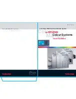
PBX
Punch-down block
Analog Wiring using RJ21 Connector
Phones
LEGEND:
Standard Twisted
Pair Cable
50-Pin Centronics
ML Cable
RJ-21 X Connector
LD2409 Voice Card
Pin 01 - Ring 01
Pin 02 - Ring 02
Pin 03 - Ring 03
Pin 04 - Ring 04
Pin 05 - Ring 05
Pin 06 - Ring 06
Pin 07 - Ring 07
Pin 08 - Ring 08
Pin 09 - Ring 09
Pin 10 - Ring 10
Pin 11 - Ring 11
Pin 12 - Ring 12
Pin 13 - Ring 13
Pin 14 - Ring 14
Pin 15 - Ring 15
Pin 16 - Ring 16
Pin 17 - Ring 17
Pin 18 - Ring 18
Pin 19 - Ring 19
Pin 20 - Ring 20
Pin 21 - Ring 21
Pin 22 - Ring 22
Pin 23 - Ring 24
Pin 24 - Ring 25
Pin 26 - Tip 01
Pin 27 - Tip 02
Pin 28 - Tip 03
Pin 29 - Tip 04
Pin 30 - Tip 05
Pin 31 - Tip 06
Pin 32 - Tip 07
Pin 33 - Tip 08
Pin 34 - Tip 09
Pin 35 - Tip 10
Pin 36 - Tip 11
Pin 37 - Tip 12
Pin 38 - Tip 13
Pin 39 - Tip 14
Pin 40 - Tip15
Pin 41 - Tip16
Pin 42 - Tip17
Pin 43 - Tip18
Pin 44 - Tip19
Pin 45 - Tip 20
Pin 46 - Tip 21
Pin 47 - Tip 22
Pin 48 - Tip 24
Pin 49 - Tip 25
On the LD2409 board, pins
1 to 24 and pins 26 to 49
are used.
Summary of Contents for TDM Recorder
Page 2: ......
Page 12: ...Getting Started Standard 3 0 12 Nortel TDM Recorder...
Page 38: ...Recorder Hardware Installation Standard 3 0 38 Nortel TDM Recorder...
Page 64: ...Recorder Software Installation Standard 3 0 64 Nortel TDM Recorder...
Page 78: ...Uninstalling and Upgrading Recorder Standard 3 0 78 Nortel TDM Recorder...
Page 94: ...Configuring Non Facility Associated Signaling Standard 3 0 94 Nortel TDM Recorder...
Page 126: ...Voice Card Configurations Standard 3 0 126 Nortel TDM Recorder...
Page 127: ......