Contents
11
Contents
Introduction ....................................................................................................... 1
Warning/Caution symbols used in this manual .................................................................. 1
Meaning of symbols used on the product ......................................................................... 2
Safety Precautions .............................................................................................. 3
WARNING.................................................................................................... 3
CAUTION..................................................................................................... 5
Notes on handling the product .............................................................................. 8
Abbreviations Used in This Manual........................................................................10
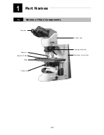
Chapter 1 Part Names.........................................................................................14
1.1
Names of Main Components ............................................................................... 14
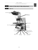
1.2
Names of Parts Used to Make Adjustments........................................................... 15
1.2.1 Right
view ................................................................................................ 15
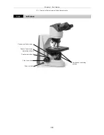
1.2.2 Left
view .................................................................................................. 16
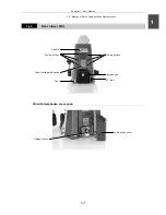
1.2.3
Rear view (50i).......................................................................................... 17
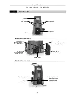
1.2.4
Rear view (55i).......................................................................................... 18
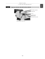
1.2.5
Ergonomic binocular tube with camera attached ............................................ 19
1.2.6
With cytodiagnostic unit attached ................................................................ 20
1.2.7
With Epi-fl attachment mounted .................................................................. 21
Chapter 2 Microscopy .........................................................................................22
2.1 Bright-Field
Microscopy ...................................................................................... 22
2.2
Microscopy with Cytodiagnostic Unit Attached....................................................... 26
2.3
Microscopy with Epi-fl Attachment Mounted.......................................................... 29
2.4 Photomicroscopy............................................................................................... 32
Chapter 3 Individual Operations ...........................................................................34
3.1 Power
ON/OFF .................................................................................................. 35
3.1.1 Microscope................................................................................................ 35
3.1.2 Cytodiagnostic
unit .................................................................................... 35
3.1.3
Light source of the Epi-fl attachment (mercury lamp)..................................... 35
3.2 Brightness
Adjustment....................................................................................... 36
3.2.1
Adjustment using the brightness control knob ............................................... 36
3.2.2
Adjustment using the preset switch ............................................................. 37
3.2.3
Adjustment with the ND filter IN/OUT lever (for 50i) ...................................... 37
3.2.4
Automatic adjustment after magnification change
(only for a 55i when a cytodiagnostic unit is attached) ................................... 38
3.2.5
Adjustment with the ND filter of the Epi-fl attachment.................................... 38
3.2.6
Transmitted image in fluorescence observation.............................................. 38
3.2.7
Camera adjustment (adjusting the brightness of the image on the monitor)...... 39
3.3
Optical Path Switching ....................................................................................... 39
3.3.1 Optical
path
distribution ............................................................................. 39
3.3.2
Disabling the clicking of the optical path switching lever ................................. 39
3.4 Vertical
Stage
Motion......................................................................................... 40
3.4.1 Prohibited
actions ...................................................................................... 40
3.4.2
Knob rotation direction and stage motion direction ........................................ 40
3.4.3
Number of knob turns and distance of stage travel ........................................ 40


