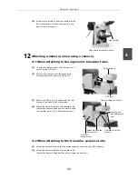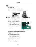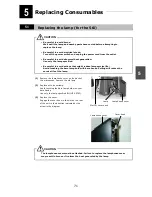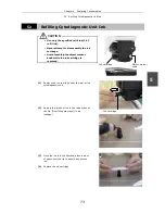
60
Assembly
4
1
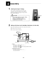
Checking the Input Voltage
Check the input voltage indicated on the back of the
microscope. Use the microscope only if this indication
matches the power supply voltage for the area in which
the microscope will be used.
If the voltage indication and supply voltage
differ, do not attempt to use the
microscope. Contact your nearest Nikon
representative to seek advice.
2
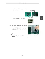
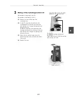
Wiring at the Rear and Installing the Battery (for the 55i)
(1)
Confirm that the power switch of the microscope is turned off.
(2)
Remove the rear wiring cover.
(3)
Connect the appropriate cables.
55i rear
Connector J1: INPUT 12V DC (+ -C
•
- – )
Connector J2: J-CY/PS
Connector J3: SWITCH (when using cytodiagnostic unit)
Connector J4: J-CY/SG
Cytodiagnostic unit rear
Connector A: INPUT 12V DC (+ -C
•
- – )
Connector B: SWITCH
CAUTION
55i rear
AC adapter
Hand switch
Cytodiagnostic
unit
Battery holder
Input voltage
indication
(2)
(1)

