Nidek Medical HandyRef-K Operator'S Manual Download Page 116

110

PARAMETER SETTINGS AND MAINTENANCE: Maintenance

5

Perform AR and KM measurements in the same manner as normal AR and KM mea-
surements to check the results.

If the measured results differ substantially from the values indicated on the spherical model eye, con-
tact NIDEK or your authorized distributor.
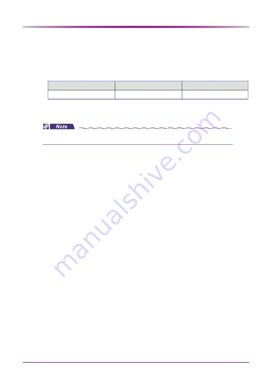
Values marked on the labels of the spherical model eye

6

After checking the results, store the spherical model eye in the spherical model eye
storage space.

Vertex Distance (VD)

Diopter

Corneal curvature radius

mm

D: 0.12D increments

mm: 0.01 mm increments

• When the VD value of the spherical model eye differs from the value set by the 

 “ 2. VERTEX D.”

(page 89)

 parameter, change the parameter setting to match that of the model eye.

Summary of Contents for HandyRef-K

Page 1: ...OPERATOR S MANUAL HANDHELD REF KERATOMETER...

Page 2: ...040 Corporate Court San Jose CA 95131 U S A United States Agent Telephone 1 800 223 9044 USA Only URL https usa nidek com NIDEK S A Europarc 13 rue Auguste Perret 94042 Cr teil FRANCE EU Authorized Re...

Page 3: ...t be thor oughly understood before using the device Keep this manual handy for reference For any problems or questions about the device please contact NIDEK or your authorized distributor Before using...

Page 4: ...the station by battery pack 35 2 5 Connecting the Main Body and Station 36 2 5 1 Connection by cable 36 2 5 2 Connection by infrared printer equipped model only 37 2 5 3 Connection by wireless LAN pr...

Page 5: ...82 3 11 1 Connecting peripheral devices 82 3 11 2 Connection with computer 84 3 11 3 Handling of barcode scanner and magnetic card reader 86 4 PARAMETER SETTINGS AND MAINTENANCE 87 4 1 Parameter Sett...

Page 6: ...IV...

Page 7: ...lause 4 2009 Ophthalmic instruments Ophthalmom eters The dioptric powers are indicated with reference wavelength d 587 56 nm In this manual signal words are used to designate the degree or level of sa...

Page 8: ...m However it is recommended to observe the following precautions when using the device Do not aim LED beams to human eyes unnecessarily Do not look into the measuring window LED light emitting section...

Page 9: ...is not exposed to water A location that is level stable surface free from vibration and bumping A location that is not exposed to direct air flow from an air conditioner A location that is not expose...

Page 10: ...nd method sufficiently to patients Before placing the device over the patient s face release the forehead rest Otherwise parts other than the forehead rest may come into contact to the patient s face...

Page 11: ...r between the patient and any other person s touching the device Use devices that comply with IEC 60601 1 in the patient environment If any device that does not comply with IEC 60601 1 is to be used u...

Page 12: ...d is connected or disconnected with the power switch on device malfunction may occur If the device is not to be used for a long time disconnect the power cord from the power outlet Maintain the surrou...

Page 13: ...quid such as water Do not use or leave the battery pack near fire or a stove 60 C or higher Do not expose the battery pack to excessive shocks such as by throwing it Do not contact the battery pack te...

Page 14: ...lithium battery used on the board circuit board plastic parts that contain brominated flame retardant LCD or power cord It is recommended to commission the disposal to a designated industrial waste d...

Page 15: ...aving While the device is in power saving the following conditions are in effect Main body The LCD and memory indicator are turned off Station The pilot lamp is turned off even if the station is power...

Page 16: ...10 SAFETY PRECAUTIONS Labels and Symbols...

Page 17: ...2 Intended use The HANDHELD REF KERATOMETER HandyRef K is a medical device which measures objective refractive errors and corneal curvature radius of the patient s eye 2 1 3 Principles Objective refra...

Page 18: ...mode 3 Print button Prints or outputs the measured results 4 Function buttons Buttons to select the five operation icons shown on the screen The corresponding icons change depending on function Select...

Page 19: ...ndow can be automatically checked using the window check function Always keep it clean 10 Start button When this button is pressed on the main screen the screen changes to the AR KM measurement screen...

Page 20: ...sh drive is connected here Measurement data can be stored to the USB flash drive and copied to a computer CAUTION Equipment connected to the analog or digital interfaces must be certified according to...

Page 21: ...ation aim the IR windows toward the IR receptor B 2 B The maximum communication distance between the main body and station is 1 m 3 Printer cover button Press this button to open the printer cover for...

Page 22: ...tdown function if there is no operation or data transmission to the station for 5 minutes When the station is turned off the pilot lamp is off before using it press to turn on the power 9 Main body ba...

Page 23: ...body and station is connected here CAUTION Equipment connected to the analog or digital interfaces must be certified according to the represen tative appropriate national standards such as EN 60601 1...

Page 24: ...rement results are displayed here Items differ depending on the measurement modes AR KM AR KM 3 Patient s eye R L The eye of the patient being displayed on the LCD is indicated by or in blue The patie...

Page 25: ...e device is not connected to WLAN Yellow icon Indicates that connection is being checked Gray icon Indicates that connection is being initialized 8 Battery level icon Indicates the battery level of th...

Page 26: ...on or off the melody A melody is played to hold a child s attention during measurement The melody stops when the print button is pressed or clearing data is complete However when the SUMMARY parameter...

Page 27: ...tion icons Function Page 3 Displays Page 1 Supine position Changes the direction in supine position mode Memory Displays the memory data screen CYL Changes CYL mode Parameter Displays the parameter sc...

Page 28: ...ng 4 Focusing indicator Indicates the distance between the main body and patient s eye to facilitate focusing 5 Axis correction icon The sensor detects the inclination of the main body to perform auto...

Page 29: ...body s inclination in horizontal direction as a reference When the main body is tilted more than 45 the number display changes to The icon is displayed when the 7 AXIS CORRECTION page 90 parameter is...

Page 30: ...Check the contents before use Part name Quantity Appearance Occluder 2 units Printer paper printer equipped model only 3 rolls Battery pack 1 unit Connection cable 2 m 1 unit Spherical model eye 1 uni...

Page 31: ...e battery pack 1 Remove the handle cover from the main body 1 Hold down on the handle cover with a fin ger 2 While holding down slide it down to remove the cover as shown to the right 2 Install the ba...

Page 32: ...the power cord to the power inlet 3 Confirm that the power switch is turned off and plug the power cord into the power outlet 4 Turn on the power switch of the station WARNING Connect the power plug t...

Page 33: ...charging is com plete If no battery pack is inserted in the main body and the main body is placed on the station the charge indicator blinks CAUTION The battery pack has a limited lifetime When the ba...

Page 34: ...switch of the station 3 With the terminals aligned as shown below insert a battery pack into the battery slot The station battery charge indicator lights up and charging starts The charge indicator go...

Page 35: ...ckle and holder 1 Pass one of the ends of the strap through the buckle The buckle has a proper orientation Pass the strap with the buckle oriented as shown to the right 2 Pass the strap through the ho...

Page 36: ...ke up any slack and check that there is no play in the strap 4 Attach the other end of the neck strap to the main body in the same manner 5 Move the buckle position to adjust the strap length for ease...

Page 37: ...extends from the cover Hold down to feed the printer paper 2 Press the printer cover on both sides to close the cover securely CAUTION Be sure to use only the printer paper 80620 00001 specified by NI...

Page 38: ...appears along the edge of the printer paper it means that the paper is running short In such a case replace the printer paper with a new roll 1 Press to open the printer cover then remove any remainin...

Page 39: ...R L Covering the eye that is not being measured facili tates patient eye fixation When the occluders are not in use place them on the occluder base of the station 4 As necessary connect peripheral de...

Page 40: ...few seconds the initial screen appears Initializa tion starts and the memory indicator blinks When initialization completes the memory indicator goes out and the screen changes to the main screen 2 Se...

Page 41: ...e than a second When the station is powered by the battery pack the station will be automatically turned off by the auto shutdown function if there is no operation or data transmission to the station...

Page 42: ...inter equipped model set the 91 STATION I F page 98 parameter to CABLE CAUTION Check the plug orientation before connecting the cable Do not connect it with excessive force During measurement make sur...

Page 43: ...ptor are in direct alignment This communication method is suitable when the device is used in a location where it is exposed to intense light such as sunlight or room illumination 1 Set the 91 STATION...

Page 44: ...1 m 2 5 3 Connection by wireless LAN printer equipped model only The main body and station communicate by wireless LAN 1 The wireless LAN communication mode is selectable between INFRA mode which requ...

Page 45: ...page 98 parameter For output to refractor select YES or NO for the 93 OUTPUT TO RT page 98 parameter 1 Static IP address only 2 Only one data set can be output to the refractor or Eye Care card at on...

Page 46: ...40 INTRODUCTION Connecting the Main Body and Station...

Page 47: ...ion Mode measurement for patients lying down page 59 3 7 Other Measurements 3 7 1 Quick measurement mode page 62 3 7 2 Cataract measurement mode page 63 3 7 3 Ring observation page 64 3 7 4 Retroillum...

Page 48: ...servation Pupil size measurement Sagittal measurement Main screen AR KM measurement All screens are accessible from either the main screen or AR KM measurement screen Exiting from any screen returns t...

Page 49: ...2 Press on the handle The AR KM measurement screen is displayed 3 Perform checks before use Before use perform the checks listed in O Checklist before use page 44 If any abnormality is found stop usi...

Page 50: ...he forehead rest is clean The neck strap is securely attached and the length is appropriately adjusted No abnormality is found when the station is turned on No abnormality is found when the main body...

Page 51: ...s displayed on the WINDOW CHECK screen 2 The following conditions are required at start up of the main body The main body is held by hand If the main body is left on the station and checked for measur...

Page 52: ...measuring window is checked for cleanliness before the first measurement every time the device is turned on Regardless of the result WINDOW CHECK OK or WINDOW CHECK NG the check is not per formed from...

Page 53: ...for the next use 4 Place the main body on the station and place the dust cover on the device To prevent accidental dropping of the device place the main body on the station whenever possible When the...

Page 54: ...ment mode among R K R and K Pressing changes the mode in the order of R K R K R K CAUTION When the device is being held for measurement be sure to use the neck strap Accidental dropping of the device...

Page 55: ...asses or contact lenses 2 Reassure the patient before measurement by explaining the following Ex This device measures your eye with infrared light to determine the lens most suitable for you The infra...

Page 56: ...5 the error indication AxC OVER is displayed and measurement is suspended Measurement resumes when the main body inclination is within 45 9 Give the following instructions to the patient Try not to bl...

Page 57: ...ye condition In such a case press to select the correct eye to be measured When the eye to be mea sured is detected automatically the R L indica tion appears in blue When the eye to be measured is set...

Page 58: ...ent s eye and aligned to the target adjust the focus 3 Measurement starts automatically by the auto shot function as soon as alignment and focusing are optimized Focusing indicator display When the ma...

Page 59: ...the steps common to all measurement modes For continuing the measurement pro cedure refer to the section for each particular mode If eyelashes obstruct the minimum pupil diameter mark AR measurement...

Page 60: ...omatically in the following order 1 KM measurement starts KM 2 A beep sounds then the KM measurement values and the number of measurements are dis played KM 3 At this point if the device remains align...

Page 61: ...the results 3 8 Printing Measured Values page 71 5 To measure a following patient continue from Step 3 in the same manner 6 To finish operation see 3 3 2 Device shutdown page 47 AR measure ment AM MO...

Page 62: ...ment The spherical power is over the measurement range of the side During KM measurement The corneal curvature radius is too small and not within the measurable limit Err COVR During AR measurement Th...

Page 63: ...evel will be increased from the second measurement When the 4 FOG MODE page 89 parameter is set to 3 fogging will be performed in each measurement 5 When the specified number of measurements is obtain...

Page 64: ...atically in the following order 1 KM measurement starts 2 A beep sounds then the KM measurement values and the number of measurements are dis played 3 At this point if the device remains aligned and i...

Page 65: ...eye to be measured needs to be selected manually The indication changes to When measuring a supine patient from their side or from above the patient make sure that the forehead rest is retracted 60 o...

Page 66: ...de 90 Measuring from above the patient 180 CAUTION When using the device in supine position mode be sure to use the neck strap to prevent the device from falling When measuring a patient lying down do...

Page 67: ...selected as default As necessary press to select the correct eye to be mea sured Right eye Select Left eye Select 4 Continue by performing the procedures for normal measurement 3 4 Operating Procedure...

Page 68: ...Adjust the main body position so that the align ment guide mark on the patient s eye comes within the target 3 Measurement starts automatically by the auto shot function as soon as the main body posit...

Page 69: ...measurement mode is canceled when or is pressed or when or is changed Sample printout for cataract measurement mode When data obtained in cataract measurement mode is printed is added next to the meas...

Page 70: ...on of the patient s eye to be observed 1 Perform AR measurement 3 5 1 AR KM measurement mode page 54 2 Display the ring image screen 1 Press to display page 2 Press The ring image obtained in the last...

Page 71: ...3 Adjust the main body position so that the opacity is in focus and the alignment guide mark is not prominent 4 Press to capture image When several images are captured the last image is saved After i...

Page 72: ...nter PS measurement mode 2 To measure the pupil size under reduced lighting press to turn off the illumination lamp 3 Adjust the main body position to bring the patient s eye into focus 4 Press to cap...

Page 73: ...o the main screen The PS measured value is displayed on the screen indicating the completion of PS measurement When the 31 PRINT page 92 parameter is set to AUTO to print pupil size PS measurement val...

Page 74: ...up Conversely when measuring the convex surface place the lens with the convex surface up 3 Put the contact lens holder on a flat table or the spherical model eye measuring holder of the station as sh...

Page 75: ...the main body position so that the target comes within the mire ring 2 Move the main body forward and backward to the position where the mire ring becomes thinnest 3 Press to start measurement The in...

Page 76: ...side TEM Temporal side NAS Nasal side A Axis of steepest meridian KM measurement FIX ANGLE Fixation angle S Sagittal data which the dRo value is added to or subtracted from sag ittal radius values e...

Page 77: ...le for printing by infrared communication Place the main body on the station then press Placing the main body on the station offers more stable communication Aim the main body toward the IR receptor B...

Page 78: ...blue on the screen for proper printing The display is changed to the main screen from other screens Printing is previously performed Even when the wireless LAN icon is displayed in blue the device may...

Page 79: ...73 OPERATING PROCEDURE Printing Measured Values Sample printout Sample printout 1 Standard printing by default Sample printout 2 Items added to the standard printing...

Page 80: ...ylinder axis 9 Confidence index The confidence index is displayed from best to worst in six levels 9 8 7 6 5 or E E indicates erroneous data 10 AR median values Printed when three or more AR measureme...

Page 81: ...val ues with the vertex distance VD at 0 mm 15 PS pupil size measured value When the chart illuminating lamp is turned on or off during manual PS measurement LAMP ON or LAMP OFF is printed out accordi...

Page 82: ...displayed for measurement of both eyes the summary screen appears To display the summary screen before is displayed for mea surement of both eyes press 2 Confirm the measured values on the sum mary s...

Page 83: ...is pressed To save data without printing set the 31 PRINT page 92 parameter to NO The saved data is stored in the main body even after the battery is drained The following data can be saved Patient ID...

Page 84: ...to display page 2 Press to display the MEMORY DATA MANAGEMENT screen 2 Select ALL PRINT with or button and press The message PRINT ALL SAVED DATA appears 3 Print all the saved data Select YES with or...

Page 85: ...PRINT is selected even if the 93 OUTPUT TO RT page 98 parameter is set to YES the data is not output to the refractor 1 Display the MEMORY DATA MANAGE MENT screen 1 Press to display page 2 Press to d...

Page 86: ...the data by page 4 Press The message PRINT SELECTED DATA appears 5 Print the selected data Select YES with or button and press to print the selected data Selecting the STOP button cancels the printin...

Page 87: ...MANAGEMENT screen 2 Select ALL CLEAR with or button and press The message DELETE ALL SAVED DATA appears 3 Delete all saved data Select YES with or button and press to delete all the saved data The me...

Page 88: ...ecting peripheral devices No Connection method connecting device Connection port Function 1 LAN LAN port of the computer AR and KM data are exported Measured data is managed by database software such...

Page 89: ...Before connecting a connection cable be sure to turn off all devices Connecting the cable with power on may cause malfunction Ensure that the plugs are securely inserted into the ports in the proper o...

Page 90: ...only set the relevant parameters for the main body and station 2 Connect the station and computer by a LAN cable then set the relevant parameters Operation procedure When measurement is complete pres...

Page 91: ...rive specified by NIDEK to the USB port at the bottom of the main body Set the parameter 32 OUTPUT W PRINT page 92 to YES Set the parameter 92 OUTPUT TO PC page 98 to USB MEM Operation procedure Perfo...

Page 92: ...data that has been printed still displayed the device recog nizes the displayed data as that of a former patient and erases it automatically The latest patient ID that was read before printing will be...

Page 93: ...ameters be sure to connect the main body and the station by the cable When any setting has been changed be sure to restart the main body and station after the screen returns to the main screen For the...

Page 94: ...hen the setting is complete press to confirm the entry The screen returns to the main screen 11 Turn off power to the main body and station When the device is turned on again the parameter changes wil...

Page 95: ...ting of devices destined for NIDEK INCORPO RATED 3 AXIS STEP Axis angle increments 1 5 Selects the display increments of AXIS 4 FOG MODE Fog mode 1 2 3 See 1 5 AM MODE AM mode YES NO Sets whether 5 AM...

Page 96: ...etting contents 11 KM UNIT Display unit of corneal curva ture radius mm D Selects the display unit of the corneal curvature radius for KM measurement from corneal curvature radius mm or corneal refrac...

Page 97: ...n the AR KM measure ment screen 22 SAGIT AXIS Sagittal cylinder axis AXIS FIX Sets whether to convert the sagittal measurement for the axis of the steep est meridian obtained by KM measurement AXIS Co...

Page 98: ...OUTPUT TO RT page 98 parameter is set to YES the data is output to the refractor 33 MEMORY PRINT Printing memory data PRINT OUTPUT BOTH Sets the output type of memory data PRINT Only printing occurs O...

Page 99: ...s selected finishing measurement for both eyes or pressing the print button displays the summary screen before the data is printed out PRINT2 parameter screen Parameter option Setting contents 51 AR P...

Page 100: ...hether to print failed AR data When set to YES errors such as blink error range over error and confidence index error are printed 57 NAME PRINT Printing of name YES NO Sets whether to provide printing...

Page 101: ...R L B AR KM B Selects the print format of measured data R L Printing occurs in the order of the right eye AR value retroillumina tion image KM value and left eye AR value retroillumination image KM v...

Page 102: ...le from among 5MIN 10MIN 15MIN and NO Before the device is automatically turned off the screen changes as fol lows After 1 minute Returns to the main screen the screen displayed at startup After 4 min...

Page 103: ...t the data READER parameter screen Parameter option Setting contents 81 READER START Position to start reading 1 to 250 Sets the reading start position for ID when the magnetic card reader is used Con...

Page 104: ...does not occur When the 91 STATION I F page 98 parameter is set to IR or NO LAN cannot be selected When the 91 STATION I F page 98 parameter is set to WLAN and the 107 WLAN MODE page 100 parameter is...

Page 105: ...P has not been obtained from the DHCP 103 STA IP Station IP address 0 to 255 0 to 255 0 to 255 0 to 255 Input the IP address of the station to communicate by a wireless LAN 104 MASK Subnet mask 0 to 2...

Page 106: ...L Wireless LAN channels Varies depending on the shipping destination the smallest number is set as the default When there is no available channel for the wireless LAN in AD HOC mode selects the wirele...

Page 107: ...mputer name or IP address of the connected computer up to 17 digits 116 FOLDER Shared folder name Up to 17 characters DATA Input the shared folder name of the connected computer up to 17 digits 117 ST...

Page 108: ...DRESS with or button and press The MAC ADDRESS screen appears it may take a few seconds before the screen appears 2 Check the MAC address If communication between the main body and station fails such...

Page 109: ...y to the station with the connection cable If the cable is not connected transfer of the parame ter settings to the station will fail and the screen shown to the right appears 1 Confirm that the cable...

Page 110: ...OCK screen is displayed 2 Set the date and time in the SET CLOCK screen 1 Press to select the item to be changed month day year time as shown in the example to the right 2 Press or to change the numer...

Page 111: ...with a maximum of two lines can be input Move the cursor or in the character list field to the desired character and press to confirm its entry 3 After changing the setting press to confirm the entry...

Page 112: ...by the connection cable and perform SET STATION again The printer operates however printed results cannot be obtained The printer paper may be loaded with the incorrect side up Set it with the correct...

Page 113: ...heck whether the communication parameters are properly set ERROR 080 to 088 COM STATION ERR Communication between the main body and the station may not be established When the connection cable is used...

Page 114: ...ified name does not exist Check the connection of the LAN cable Or check that the specified computer name is correct ERROR 756 CAN T LOGON PC ERROR 956 CAN T LOGON PC WLAN Cannot log on to the compute...

Page 115: ...ion changes to or Either eye R L may be selected ERROR 772 NO NETWORK ACK ERROR 972 NO NETWORK ACK WLAN Acknowledgment error The file is deleted within 5 seconds or not renamed Check whether the captu...

Page 116: ...tact NIDEK or your authorized distributor Values marked on the labels of the spherical model eye 6 After checking the results store the spherical model eye in the spherical model eye storage space Ver...

Page 117: ...ow off any dust on the measuring window with a blower 2 Wrap lens cleaning paper around a thin stick or cotton swab and wipe the lens of the measuring window with a material moist ened with alcohol CA...

Page 118: ...ly 1 Press to open the printer cover and remove the printer paper 2 Apply the nozzle of a vacuum cleaner to the auto cutter to remove paper residue Never blow off paper residue with a blower If paper...

Page 119: ...orneal cylindrical power 0 to 12 00 D 0 12 0 25 D increments Corneal cylinder axis 0 to 180 1 5 increments The measuring accuracy is in accordance with Type B ISO 10343 Pupil size measure ment 1 0 to...

Page 120: ...H mm Mass 2 7 kg printer equipped model 2 5 kg model without printer Wireless LAN The wireless LAN module incorporated in this device conforms to the regional regulations of Japan the USA Canada Sing...

Page 121: ...ck Class I ME equipment Protection against electrical shock applied parts Type B applied part Protection against harmful ingress of water or particulate matter IPX0 Suitability for use in an oxygen ri...

Page 122: ...ot been obtained and contact lens conversion values Auto shot This function automatically starts measurement as soon as alignment and focus ing become optimum Vertex distance VD The distance between t...

Page 123: ...nsformer between the medical electrical equipment and network devices such as a network switch and between the network devices and other electri cal equipment Electric shock may result For installatio...

Page 124: ...th CISPR 32 Class B Computer Complied with CISPR 32 Class B O Essential performance Objective refraction function Keratometry measurement function Part name Connector shielded Cable shielded Ferrite c...

Page 125: ...e level Electromagnetic environment guidance Electrostatic Discharge ESD IEC 61000 4 2 8 kV contact 2 kV 4 kV 8 kV 15 kV air 8 kV contact 2 kV 4 kV 8 kV 15 kV air Floor should be wood concrete or cera...

Page 126: ...cts and people a Field strengths from fixed transmitters such as base stations for radio cellular cordless telephones and land mobile radios amateur radio AM and FM radio broadcast and TV broadcast ca...

Page 127: ...ted or operated in conjunction with any other antenna or transmitter Station precautions This equipment complies with FCC IC radiation exposure limits set forth for an uncontrolled environment and mee...

Page 128: ...122 SPECIFICATIONS AND TECHNICAL INFORMATION EMC Electromagnetic Compatibility...

Page 129: ...ftware The license granted herein will not be intended as or construed to be any assignment of the rights of NIDEK or the owner of the Third Party Software The Software and the Third Party Software ar...

Page 130: ...court having jurisdiction thereof 10 SEVERABILITY 10 1 If any provision or any portion of any provision of this Agreement will be held to be invalid or unenforceable that provision will be severed fro...

Reviews: