2-4 General Description
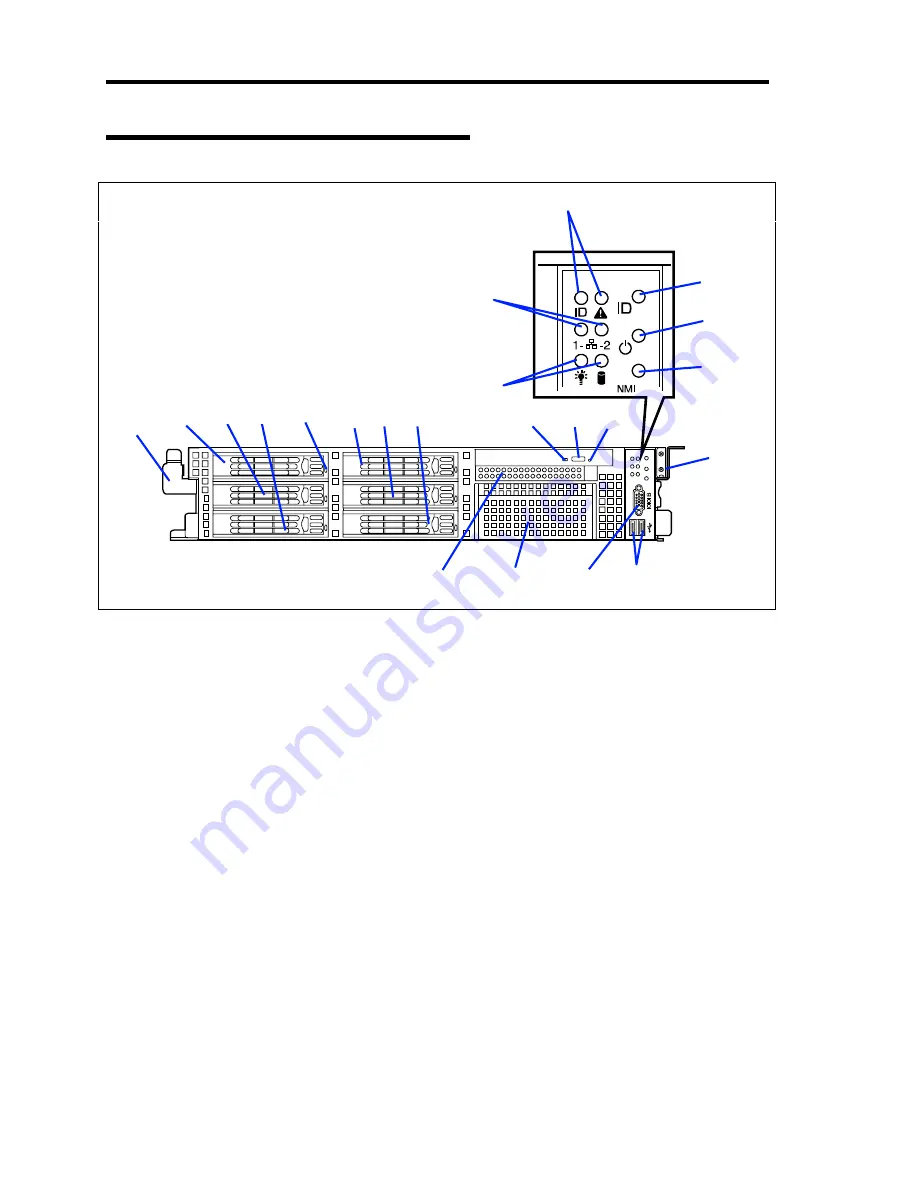
Front View with Front Bezel Removed
0
1
2
3
4
5
1 Handles (1 at the right and left each)
Hold the handles when dismounting/mounting the server from/in the rack.
2 Hard disk drive bays
Mount hard disk drives in the bays. Each number following the bold-faced number indicates
the port number. In the standard configuration, the hard disk drive trays are mounted in all the
bays.
3 DISK LED (green/amber)
Hard disk drive LED. Each hard disk drive LED is green during access to the hard disk drive.
The LED turns amber when the hard disk drive fails. The LED flashes switching back and forth
between green and amber during build processing (only in RAID System).
4 optical disk drive
This drive reads data from the disc.
4
-1 Emergency hole
4
-2 Disk access LED
4
-3 Tray eject button
5 USB connectors (2 ports)
Connect device compliant with the USB interface to the connectors.
1
2
-0
2
-1
2
-2
3
2
-3
2
-4
2
-5
4
-2
4
-3
4
-1
7
6
5
1
9
10
11
12
12
12
8
Summary of Contents for Express5800/120Rj-2
Page 16: ...x This page is intentionally left blank ...
Page 19: ...Notes on Using Your Server 1 3 Internal View ...
Page 34: ...1 18 Notes on Using Your Server This page is intentionally left blank ...
Page 90: ...3 24 Setting Up Your Server This page is intentionally left blank ...
Page 164: ...4 74 Configuring Your Server 3 Setting menu for VD 0 is displayed ...
Page 172: ...4 82 Configuring Your Server This page is intentionally left blank ...
Page 240: ...7 12 Maintenance This page is intentionally left blank ...
Page 354: ...9 78 Upgrading Your Server This page is intentionally left blank ...
Page 364: ...C 2 IRQ This page is intentionally left blank ...
Page 412: ...E 24 Installing Windows Server 2003 This page is intentionally left blank ...
Page 414: ...F 2 Using a Client Computer Which Has a CD Drive This page is intentionally left blank ...
Page 418: ...G 4 Product Configuration Record Table This page is intentionally left blank ...


