2-4 General Description
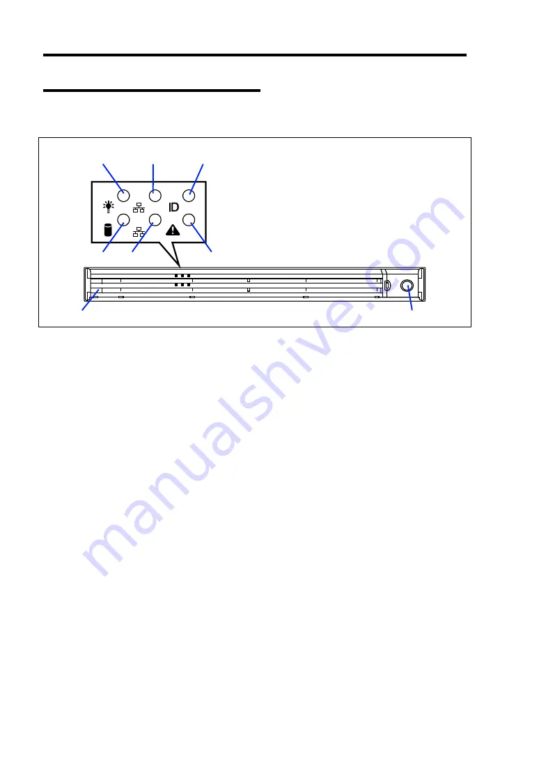
Front View with Front Bezel Closed
The following figure shows the location of the front system features.
1 Front bezel
The front bezel is a cover protecting the front devices during daily operation. A security key
is provided to lock the cover.
2 Key slot
Insert the security key into this slot when unlocking the front bezel.
3 POWER LED (green)
This LED turns green when the power is turned on.
4 DISK ACCESS LED (green/amber)
This LED is green during access to the internal hard disk drives. The LED turns amber when
even one of the internal hard disk drives fails.
5 ACT LED (green)
This LED is on while the system is connected to the network. The number "1" on the icon
indicates LAN port 1, and the number "2" indicates LAN port 2.
6 UID LED (blue)
This LED goes on when the UID switch is pressed. (The LED also goes on or flashes when
software issues a command.)
7 STATUS LED (green/amber) (on the front panel)
This LED indicates the server status. The LED is green during normal operation. The LED
turns amber or flashes when the server enters the abnormal state.
3
5
-1
6
7
5
-2
4
1
2
Summary of Contents for Express5800/120Rf-1
Page 32: ...1 16 Notes on Using Your Server This page is intentionally left blank ...
Page 154: ...4 58 Configuring Your Server This page is intentionally left blank ...
Page 236: ...6 26 Installing and Using Utilities This page is intentionally left blank ...
Page 248: ...7 12 Maintenance This page is intentionally left blank ...
Page 348: ...C 2 IRQ This page is intentionally left blank ...
Page 408: ...G 4 Product Configuration Record Table This page is intentionally left blank ...


