


4 Product description
Maschinenfabrik Reinhausen GmbH 2020
27
3587317/21 EN
TAPCON
®
Remote mode (REMOTE)
In remote mode, you can make entries and issue commands using digital in-
puts or the control system, depending on the setting of the Remote behavior
[
AVR AUTO
AVR MANUAL
LOCAL
REMOTE
LOCAL
REMOTE
Automatic regulation
Yes
Yes
No
No
Tap-change operation via
operating controls
No
No
Yes
No
Tap-change operation via
inputs
No
No
No
Yes
2)
Tap-change operation via
SCADA
1)
No
No
No
Yes
2)
Value adjustment via
SCADA
1)
No
Yes
No
Yes
2)
Table 8: Overview of operating modes
1)
Optional when connecting TAPCON® to a control system (SCADA)
2)
You can use the Remote behavior [
Page 90] parameter to set the be-
havior
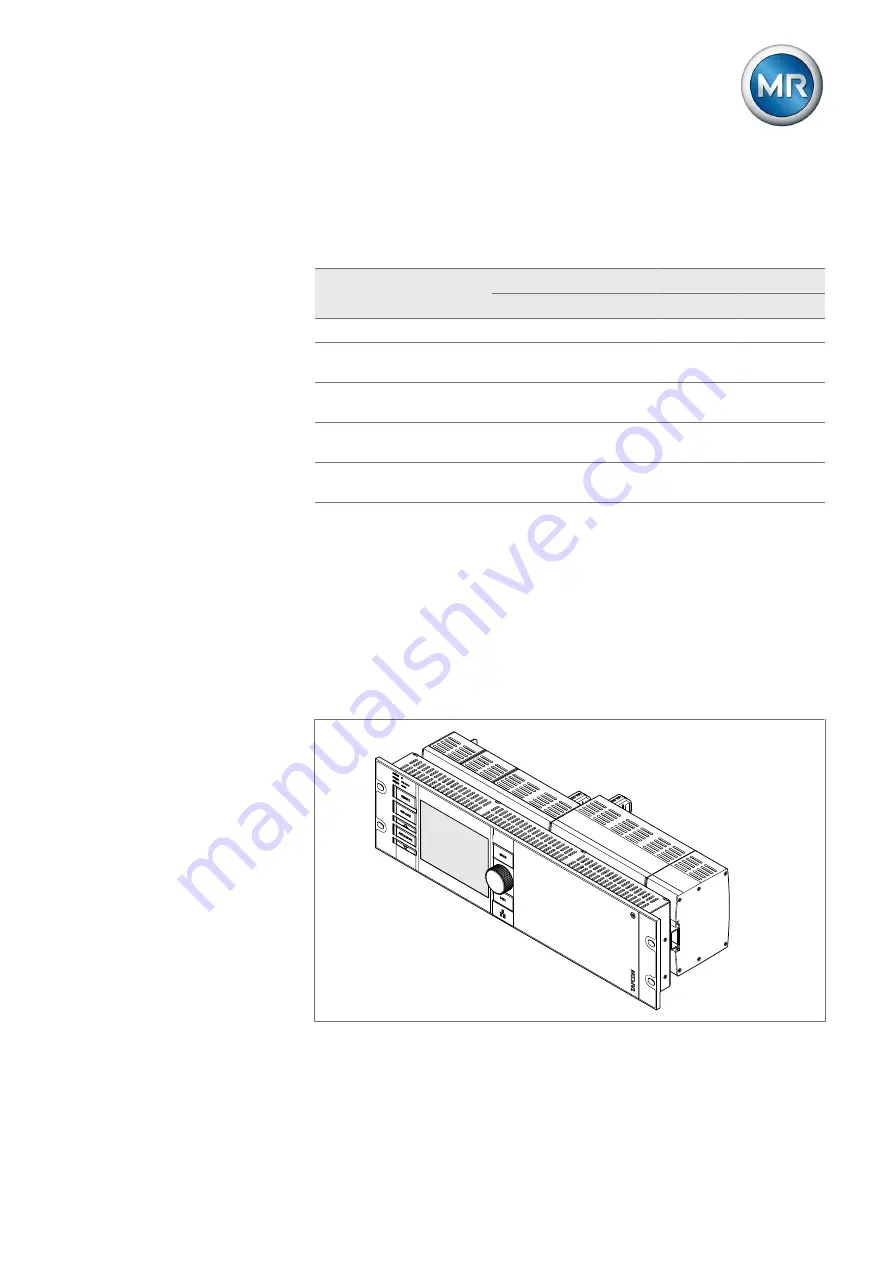
4.6 Design
Depending on the order, the device is either designed as a 19-inch plug-in
housing or supplied as individual components for assembly on a cap rail.
The individual device assemblies are described in the following section.
Figure 4: 19-inch plug-in housing
Summary of Contents for TAPCON
Page 1: ...Voltage regulator TAPCON Operating Instructions 3587317 21 EN ...
Page 333: ......


