Chapter 13. Physical Layer Interface Controller (PLIC)
13-9
GCI/IDL Block
13.2.3.5 GCI/IDL D-Channel Contention
Typically, when the CPU wants to transmit a D-channel packet, it starts the HDLC framer.
In IDL mode, when the CPU can start sending data from the prepared HDLC frame to the
D-channel transmit register, it asserts DREQ by setting the appropriate DRQ bit in the
PDRQR register. The D-channel controller hardware looks for a valid DGRANT back from
the layer 1 transceiver and, assuming DREQ is also valid, begins transmitting the
D-channel packet. PDCSR[DGn] reflects the value of the dedicated DGRANT pin. Refer
to the MC145574 data sheet for SCIT mode information.
In GCI mode the only D-channel contention control is provided by PLCRn[G/S],
Section 13.5.7, “Port Configuration Registers (P0CR–P3CR).” Provided the PLIC operates
in SCIT mode, PDCSR[DGn], Section 13.5.19, “D-Channel Status Register (PDCSR),” is
defined by the state of PLCRn[G/S], and is used to control D-channel transmission along
with PDRQR[DRQn], Section 13.5.20, “D-Channel Request Register (PDRQR).” In GCI
mode, the PLIC ports do not support any other form of D-channel contention such as the
indirect mode found on the Motorola MC145574. In GCI mode, the DGRANT pin function
found in IDL mode is disabled and the pin can be defined for other functions. Please note
that the D-channel periodic interrupts in both the receive and transmit direction are not
disabled even though the shift register is disabled by DREQ, DGRANT, and
PDRQR[DCNTIn] (Section
13.5.20, “D-Channel Request Register (PDRQR)”)
configuration.
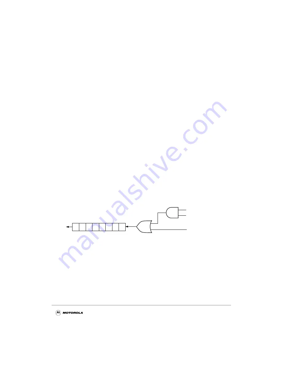
An override mechanism for D-channel contention control is provided through the
D-channel ignore DCNTI bit.
Figure 13-8 illustrates this functionality:
Figure 13-8. D-Channel Contention
13.2.4 GCI/IDL Looping Modes
The PLIC ports can be configured to operate in various looping modes as shown in
Figure 13-9. These modes are useful for local and remote system diagnostic functions.
The loopback modes are independent signal loopbacks for the respective ports. These
loopbacks allow for the echoing of local or remote information. In auto-echo or
remote-loopback modes there is no time switching or time slot assignment function. All
data received on Din is transmitted on Dout during the same time slot. Similarly, in
Shift Register Enable
DGRANT
DREQ
DCNTI
Summary of Contents for DigitalDNA ColdFire MCF5272
Page 1: ...MCF5272UM D Rev 0 02 2001 MCF5272 ColdFire Integrated Microprocessor User s Manual ...
Page 38: ...xxxviii MCF5272 User s Manual TABLES Table Number Title Page Number ...
Page 58: ...1 10 MCF5272 User s Manual MCF5272 Specific Features ...
Page 90: ...2 42 MCF5272 User s Manual Exception Processing Overview ...
Page 96: ...3 6 MCF5272 User s Manual MAC Instruction Execution Timings ...
Page 158: ...5 46 MCF5272 User s Manual Motorola Recommended BDM Pinout ...
Page 184: ...7 12 MCF5272 User s Manual Interrupt Controller Registers ...
Page 338: ...13 44 MCF5272 User s Manual Application Examples ...
Page 414: ...18 6 MCF5272 User s Manual PWM Programming Model ...
Page 452: ...19 38 MCF5272 User s Manual Power Supply Pins ...
Page 482: ...20 30 MCF5272 User s Manual Reset Operation ...
Page 492: ...21 10 MCF5272 User s Manual Non IEEE 1149 1 Operation ...


