background image

Release 1.0

Configuring BGP

526360-001-00 Rev. B

MGBI

12-9

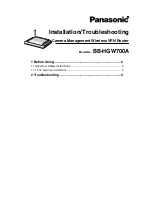
Figure 12-3  Advertising Networks in an AS

Configuring Advanced BGP Connectivity

The following are advanced BGP connectivity configuration tasks:

Configuring BGP Peer Groups

Configuring a Routing Domain Confederation

Configuring Route Flap Dampening

Shutting Down a Neighbor or Peer Group

3.3.3.2

AS100

162.56.0.0

2.2.2.2

Miami 

LA 

Chicago

AS 300

162.24.0.0

AS 100

126.60.0.0

3.3.3.1

2.2.2.1

Summary of Contents for BSR 2000

Page 1: ...BSR 2000 Configuration and Management Guide 526360 001 00 Rev B Release 1 0 MGBI ...

Page 2: ...n of such revision or change Motorola provides this guide without warranty of any kind either implied or expressed including but not limited to the implied warranties of merchantability and fitness for a particular purpose Motorola may make improvements or changes in the product s described in this manual at any time Motorola and the stylized M logo are registered trademarks of Motorola Inc Broadb...

Page 3: ...ecte n est disponible veuillez appeler le Service clientèle de Motorola qui vous apportera son assistance Umweltschutz durch Recycling Wenn Sie dieses Zeichen auf einem Produkt von Motorola sehen entsorgen Sie das Produkt bitte nicht als gewöhnlichen Haus oder Büromüll Recycling bei Geräten von Motorola Bitte entsorgen Sie dieses Produkt nicht als gewöhnlichen Haus oder Büromüll In einigen Ländern...

Page 4: ...y zbierania odpadów elektrycznych i elektronicznych informacje o utylizacji należy uzyskać od biura obsługi klienta firmy Motorola Motorola Customer Service Beskyttelse af miljøet med genbrug Når du ser dette symbol på et Motorola produkt må produktet ikke bortskaffes sammen med husholdning saffald eller erhvervsaffald Genbrug af dit Motorola udstyr Dette produkt må ikke bortskaffes sammen med hus...

Page 5: ...latba a helyi hatóságokkal a lakóhelyén alkalmazott gyakorlattal kapcsolatos információért Amennyiben gyûjtõrendszer nem elérhetõ hívja a Motorola Ügyfélszolgálatot segítségért Kujdesja per ambientin rrethues me ane te perdorimit te perseritur Neqoftese shikoni kete simbol ne produktin Motorola mos e hidhni tej produktin duke prishur keshtu ambi entin e duke shkaktuar humbje komerciale Perdorimi i...

Page 6: ... Motorola Motorola Motorola Motorola Motorola Motorola Motorola Motorola Motorola ...

Page 7: ...ltiservice Support 1 2 Network Management and Control 1 2 2 Using the Command Line Interface Overview 2 1 Using a Console Session to Access the CLI 2 2 Using a Telnet Session to Access the CLI 2 3 CLI Command Modes 2 3 User EXEC Mode 2 4 Privileged EXEC Mode 2 5 Global Configuration Mode 2 5 Interface Configuration Mode 2 6 Service Class Configuration Mode 2 6 PacketCable Configuration Mode 2 6 ...

Page 8: ...s 2 14 Using the Command History 2 15 Setting the Command History Buffer Size 2 15 Recalling Commands 2 15 Disabling the Command History Feature 2 16 Using Output Modifiers to Limit Show Command Output 2 16 Getting Help 2 17 Context sensitive Help 2 17 3 Configuring the System Overview 3 1 Initial Configuration Tasks 3 2 Gathering Network Information 3 2 Required Servers 3 2 Accessing the CLI to S...

Page 9: ...Logging Buffer 3 22 Configuring Logging Reports 3 23 Configuring EVT Logging 3 25 EVT Logging Default Configurations 3 26 Configuring EVT Logging 3 26 Displaying EVT Counts 3 28 Clearing EVT Counts 3 28 Disabling EVT Logging 3 28 Restoring EVT Default Logging Configurations 3 29 Disabling Logging of Specific DOCSIS Error Messages 3 29 Disabling the DOCSIS Ranging CM Retries Message 3 29 Disabling ...

Page 10: ...ing SSH Parameters 3 46 Viewing and Logging out SSH Sessions 3 49 Enabling RADIUS services for SSH Password Authentication 3 49 Troubleshooting Your SSH Configuration 3 49 Configuring TACACS 3 50 Configuring TACACS Servers 3 51 Enabling AAA 3 55 Configuring AAA Authentication 3 55 Configuring AAA Authorization 3 56 Configuring AAA Accounting 3 57 Displaying TACACS Information 3 59 Clearing TACACS ...

Page 11: ... Destination IP Address 4 9 Specifying Specific Trap Types 4 10 Specifying SNMP Trap Versions 4 11 Enabling Informs 4 12 Enabling Traps 4 12 Enabling CMTS Traps 4 13 Restricting Trap Rates 4 14 Disabling Traps 4 15 Configuring a Loopback Interface for an SNMP Trap Source 4 16 Trap Configuration Examples 4 16 Disabling SNMP 4 19 Configuring SNMPv3 4 19 Configuring SNMP Server Identification 4 24 Co...

Page 12: ...back Interface 5 8 Adding a Permanent ARP Entry and Timeout Value 5 10 Reverse ARP 5 11 Address Resolution Using Proxy ARP 5 12 Configuring Broadcast Addressing 5 12 Configuring the MTU 5 13 Configuring Static Routes 5 13 Clearing Route Table Entries 5 14 Configuring the Internet Control Message Protocol 5 15 About IRDP 5 15 Enabling IRDP 5 16 Managing IRDP 5 16 Enabling ICMP 5 17 Tracing a Route ...

Page 13: ...ving Host Authorization for an IP Range of CPEs 6 14 Displaying Host Authorization Information 6 15 Using DHCP Lease Query Function to Secure the Cable Network 6 16 Setting ARP Parameters 6 18 Configuring a DOCSIS 2 0 Upstream Logical Channel 6 19 About DOCSIS 2 0 6 19 Logical Channels 6 20 Channel Types 6 20 DOCSIS 2 0 Only Channel Types 6 21 Other Channel Types 6 21 Logical Channel Operation 6 2...

Page 14: ... File System 6 35 Signal to Noise Ratio Measurement 6 36 Configuring SNR Measurement 6 36 Configuring an Automatically Repeated SNR Test 6 38 Displaying the SNR Configuration 6 39 Starting SNR Measurement 6 39 Storing SNR Measurement Data 6 40 Displaying SNR Measurement Data 6 40 Retrieving SNR Data from an Operational CMTS Module 6 41 Retrieving SNR Data from a File System 6 41 Configuring an SNR...

Page 15: ... Modulation Profile Numbering Scheme 6 61 Displaying Configured Modulation Profiles 6 62 Determining the Modulation Profile Applied to an Upstream Port 6 63 Modulation Profile Configuration Mode 6 64 Entering Modulation Profile Configuration Mode 6 65 Configuring a Modulation Profile 6 66 Configuring a Modulation Profile with the iuc Command 6 66 Configuring a Modulation Profile Through an IUC Sub...

Page 16: ... Removing CMs from the Offline List 6 87 Setting the Insertion Interval for CMs 6 88 Setting the Synchronization Interval 6 88 Setting CM Authentication Parameters 6 89 Restoring Previously Defined Authentication Parameters 6 91 Denying Access to a Cable Modem 6 91 Setting the Maximum Number of Hosts 6 92 Configuring Baseline Privacy 6 93 Setting TEK Privacy 6 94 Setting Authorization Key Values 6...

Page 17: ...e Timeout for Dynamic Service Flows 6 126 Viewing QoS Information 6 126 Displaying the Packet Classifier 6 127 Displaying SFID and QoS Information 6 127 Displaying Service Flow Statistics 6 128 Displaying Upstream Service Flow Statistics 6 128 Displaying Payload Header Suppression Entries 6 128 Displaying Class of Service Qos Profiles 6 129 Configuring the BSR 2000 for DOCSIS 1 0 Interoperability ...

Page 18: ...ing Spectrum Management Hopping Actions 6 159 Viewing the Spectrum Management Roll back Function 6 162 Using Flap Lists 6 163 Setting Flap List Parameters 6 164 Using Flap Lists to Troubleshoot CM Problems 6 166 Viewing Flap List Statistics to Identify Network Health 6 167 Interpreting Flap List Statistics 6 170 Tips for Administering Flap Lists 6 174 Managing Multicast Maps 6 175 Pinging a Cable ...

Page 19: ...3 Viewing CM Information 6 193 Multiple IP Addresses Per MAC Address 6 205 Viewing the Timing Adjustments for CMs 6 206 Displaying Modulation Profiles 6 207 Viewing the Timing Adjustments for CMs 6 208 Displaying BPI Configuration Settings 6 209 7 Configuring PacketCable Overview 7 1 PacketCable and PacketCable Multimedia Components 7 1 Configuration Task Summary 7 3 Common Network Configuration T...

Page 20: ...olicy Database Policy Entries 7 25 Displaying the IPSec Configuration 7 25 Controlling Electronic Surveillance 7 26 Displaying Electronic Surveillance Information 7 27 Configuring PacketCable Specific Parameters 7 29 Enabling DQoS 7 29 Configuring DQoS Parameters 7 31 Configuring DQoS Gate T0 and T1 Timers 7 31 Displaying Gates 7 32 Displaying Gate Statistics 7 35 Configuring PacketCable Multimedi...

Page 21: ...icy Based Routing 8 14 Configuring a Policy Based Route Map 8 15 Defining Match Criteria 8 15 Defining the Route 8 15 Enabling Policy Based Routing on an Interface 8 17 Enabling Local Policy Based Routing on a Router 8 18 Gathering Routing Policy Information 8 18 9 Configuring IP Multicast Routing Overview 9 1 Enabling IP Multicast Routing on the BSR 9 2 Configuring PIM 9 2 About PIM 9 3 Enabling ...

Page 22: ...t Group Member 9 12 Managing IP Multicast Routing on the BSR 9 12 Configuring an IP Multicast Static Route 9 13 Changing the Distance for a Unicast Multicast Route 9 13 Changing the Distance for a Static Multicast Route 9 14 Clearing IP Multicast Information 9 14 Clearing IGMP Statistics 9 14 Removing the IP Multicast Cache 9 14 Gathering IP Multicast Information 9 15 Displaying General IP Multica...

Page 23: ...PF Area Authentication Parameters 11 5 Configuring OSPF Stub Areas 11 6 Configuring OSPF Not So Stubby Area 11 8 Configuring Route Summarization between OSPF Areas 11 9 Configuring Route Summarization into OSPF Area 11 10 Managing OSPF on the BSR 11 11 Establishing a Virtual Link 11 11 Assign a Default Route for an ASBR 11 14 Controlling OSPF Link Cost Metrics 11 15 Allowing Dynamic OSPF Virtual L...

Page 24: ...an AS 12 8 Configuring Advanced BGP Connectivity 12 9 Configuring BGP Peer Groups 12 10 Configuring a Routing Domain Confederation 12 12 Configuring Route Flap Dampening 12 14 Global Route Flap Dampening 12 15 Policy based Route Flap Dampening 12 15 Clearing Route Flap Dampening 12 16 Shutting Down a Neighbor or Peer Group 12 16 Enabling Message Digest 5 Authentication Between Peers 12 18 Setting ...

Page 25: ...ing the Local Preference 12 41 Configuring the Origin Attribute 12 43 Configuring the AS path Attribute 12 45 Configuring the MED Attribute 12 46 Configuring the Community Attribute 12 49 Configuring Routing Policy 12 49 Match and Set Statements 12 50 Handling Access Lists 12 52 Configuring an Access List 12 52 Configuring an AS Path Access List 12 53 Creating a Community List 12 54 Redistributing...

Page 26: ...ing VLAN Stacking through an Enhanced Bridge Mode TLV 13 9 Enabling VLAN Stacking through the CLI 13 10 Configuring VLAN Tagged Routing 13 11 Configuring the External L2 L3 Switch 13 12 Bridging Packet Sizes 13 13 Displaying VLAN Tagging Statistics 13 13 Clearing VLAN Tagging Statistics 13 14 A Pre Defined Modulation Profiles Introduction A 1 Index ...

Page 27: ...all maintain or replace the BSR 64000 Documentation Set The following documents comprise the BSR 2000 documentation set BSR 2000 Command Reference Guide This document contains the Command Line Interface CLI commands for managing configuring and maintaining the BSR 2000 BSR 2000 Configuration and Management Guide This document provides the instructions and procedures for configuring and managing th...

Page 28: ...y angle brackets must be replaced by the text the argument represents In the example 54 89 345 71 replaces ip address When entering the argument do not type the angle brackets bar brackets disable level Bar brackets enclose optional arguments The example indicates you can use the disable command with or without specifying a level Some commands accept more than one optional argument When entering t...

Page 29: ...ntains tips suggestions and other helpful information such as references to material not contained in the document that can help you complete a task or understand the subject matter Caution The exclamation point within an equilateral triangle is intended to alert the user to the presence of important installation servicing and operating instructions in the documents accompanying the equipment Warn...

Page 30: ...contact the Motorola Technical Response Center TRC The TRC is on call 24 hours a day 7 days a week In addition Motorola Online offers a searchable solutions database technical documentation and low priority issue creation and tracking Inside the U S 1 888 944 HELP 1 888 944 4357 Outside the U S 1 215 323 0044 Motorola Online http businessonline motorola com ...

Page 31: ...agreements SLAs It delivers traffic shaping for end to end SLAs across Hybrid Fiber Coax HFC infrastructure Flexible management interfaces offer automated provisioning for accelerating service delivery The high density BSR reduces headend congestion and streamlines operations and management providing four times the performance for roughly a quarter of the cost and a quarter of the rack space Flexi...

Page 32: ...ive classes of entertainment and business services including but not limited to the following IP telephony Interactive multiplayer gaming On demand music audio and video Tiered data services Application hosting Network Management and Control The BSR offers several management control and administration options The BSR supports Simple Network Management Protocol SNMP All appropriate standard MIBs an...

Page 33: ...sks and to configure protocols and physical layer interfaces for the BSR For detailed information on CLI commands refer to the BSR 2000 Command Reference Guide This chapter discusses the following topics Using a Console Session to Access the CLI Using a Telnet Session to Access the CLI CLI Command Modes Editing and Navigating with the CLI Disabling and Resetting Commands Using Command Aliases Usin...

Page 34: ...A physical connection exists between the BSR and the terminal or PC The console settings for the terminal or PC are set as shown in Table 2 1 To start a console CLI session do the following 1 Connect to the BSR The console session begins The MOT prompt displays 2 Enter the enable command and press the Enter key MOT enable Enter A Password prompt displays 3 Enter the password and press the Enter ke...

Page 35: ...d EXEC mode For a detailed discussion of the different command line modes refer to the CLI Command Modes section CLI Command Modes The command line interface is organized into different command modes Each command mode has its own set of commands available for configuring and monitoring the BSR and network operations Table 2 2 provides details on entering each command mode the prompt display naviga...

Page 36: ...hich has a limited set of commands To have access to all EXEC commands you must enter Privileged EXEC mode which is usually password protected From Privileged EXEC mode you can access Global Configuration mode which is the gateway to all other configuration modes User EXEC Mode When you first access the CLI you are initially in the User EXEC mode indicated by the MOT prompt User EXEC commands are ...

Page 37: ...mmand to return to User EXEC mode as follows MOT disable Global Configuration Mode Global Configuration commands apply to features that affect the entire system These commands enable system features and routing functions The following command example shows how to enter Global Configuration mode mode from Privileged EXEC mode MOT configure Enter MOT config To exit Global Configuration mode and retu...

Page 38: ...Privileged EXEC mode press Ctrl Z Service Class Configuration Mode Service Class Configuration mode is accessed from a cable interface Upstream and downstream QoS parameters can be configured on the cable interface for new or default service classes The following command example shows how to enter Service Class Configuration mode from Global Configuration mode MOT config cable service class Enter ...

Page 39: ...uter Configuration mode is used to configure BGP OSPF PIM and RIP routing protocol features From Global Configuration mode enter Router Configuration mode by entering any router command The prompt changes in relation to the specific protocol refer to Table 2 2 The following command example shows how to enter Router Configuration mode for RIP from Global Configuration mode MOT config router rip Ent...

Page 40: ... spectrum group to an upstream port and evaluate spectrum performance The following command example shows how to enter Cable Spectrum Group mode from Global Configuration mode MOT config cable spectrum group WORD MOT config spcgrp WORD WORD the name of the which will also be reflected in the prompt i e MOT config spcgrp newgroup To exit Cable Spectrum Group mode and return to Global Configuration ...

Page 41: ... Telnet MOT To exit the CLI enter the logout or exit commands To enter Privileged EXEC mode enter the enable or login command Privileged EXEC Enter the User EXEC enable or login command MOT To return to User EXEC mode enter the disable command Global Configuration Enter the Privileged EXEC configure command MOT config To return to Privileged EXEC mode enter the exit or end command or press Ctrl Z ...

Page 42: ...lobal Configuration mode enter the router command MOT config bgp MOT config ospf MOT config pim MOT config rip The prompt is protocol dependent Route Map Configuration From Global Configuration mode enter the route map WORD command WORD is the route map name MOT config rmap Cable Spectrum Group From Global Configuration mode enter the cable spectrum group WORD command WORD is the spectrum group na...

Page 43: ...s section describes how to do the following Moving the Cursor on the Command Line Partial Command Names Deleting Command Line Entries Scrolling Down a Line or a Screen Changing Case PacketCable Configuration From Global Configuration mode enter the packet cable command MOT config pktcable To return to Global Configuration mode enter the end or exit command To return to Privileged EXEC mode press C...

Page 44: ...story Note The CLI provides a wraparound feature for commands that extend beyond a single line on the screen When the cursor reaches the right margin the command line shifts to the left but you can scroll back to the beginning of the command Table 2 3 Cursor Movement Keys Pressing Function Ctrl B Moves the cursor backward one character Left Arrow Moves the cursor backward one character The cursor ...

Page 45: ... scroll down and view this information Changing Case To change a word to all uppercase or lowercase use the keys in Table 2 6 Table 2 4 Deletion Keys Press Function Backspace key Erases the character to the left of the cursor Ctrl W Deletes the word to the left of the cursor Delete key Erases the character to the left of the cursor Esc D Deletes the word to the left of the cursor Table 2 5 Scroll ...

Page 46: ...l Configuration mode creates an alias for a User EXEC mode command MOT config alias exec WORD WORD where WORD is the alias name for the command WORD is the name of the command being replaced by the alias The alias priv command used in Global Configuration mode creates an alias for a Privileged EXEC mode command MOT config alias priv WORD WORD where WORD is the alias name for the command WORD is na...

Page 47: ...tory The CLI provides a record or history of command entries This feature redisplays long or complex commands or entries including access lists This section describes using the command history feature to complete the following tasks Setting the Command History Buffer Size Recalling Commands Disabling the Command History Feature Setting the Command History Buffer Size By default the history buffer ...

Page 48: ...XEC mode to display the last several commands Disabling the Command History Feature The command history feature is automatically enabled To disable it during the current session use the no history command in User EXEC or Privileged EXEC mode MOT no history Using Output Modifiers to Limit Show Command Output Filters or output modifiers display specific show command information using the pipe charac...

Page 49: ...ach command mode You can enter the question mark with the complete command or its unique abbreviation For example to obtain help for the show users command you can enter show users If the CLI detects an error a the command line it positions a caret symbol at the error Context sensitive Help Display a list of command associated keywords and arguments by using the context sensitive help features To ...

Page 50: ......

Page 51: ... this chapter refer to the BSR 2000 Command Reference Guide This chapter discusses the following topics Initial Configuration Tasks Controlling Telnet and Console Access Configuring Logging Sending Messages to BSR Users Configuring Server Related Parameters Downloading Software Upgrading BSR System Software Specifying the System Image File Boot Location Saving and Viewing Your Configuration Saving...

Page 52: ...ration of the BSR you should determine the following information Interface IP address es and subnet mask s Time of Day Server IP address DHCP Server IP address Cable Modem CM authentication string or hexadecimal key information contained in the CM configuration file You must have this information when you configure authentication parameters on the BSR Required Servers The following servers are req...

Page 53: ... from a console session in order to configure password privileges for enabled modes and telnet 1 Start your terminal or terminal application to connect to the BSR Refer to Chapter 2 for more information on configuring your terminal or terminal application 2 Power on the BSR 2000 3 The terminal session begins and the password prompt displays The password is a null value by default Press the Enter k...

Page 54: ...r cannot be the first character Spaces are valid password characters if enclosed with double quotes The and characters must not be used The user must enter the correct password to gain access to the BSR and privileged level commands Follow these steps to configure the BSR system passwords 1 Automatic encryption is disabled by default If you want to encrypt all currently unencrypted passwords and a...

Page 55: ...re WORD is the user defined password that is no more than 31 characters 3 To set the password for a telnet session that allows access to the BSR in User EXEC mode use the password telnet command in Global Configuration mode MOT config password telnet WORD where WORD is the user defined password for the BSR that is no more than 31 characters 4 To set the Privileged EXEC password use the enable pass...

Page 56: ...SR ethernet X 0 and Y is the Ethernet Fast Ethernet IEEE 802 3 port number on the BSR gigaether X 0 and Y is the Gigabit Ethernet port number on the BSR loopback 1 64 is the loopback interface number turns on output modifiers filters begin filters for output that begins with the specified string exclude filters for output that excludes the specified string include filters for output that includes ...

Page 57: ... for defining a user account username nopassword username password username privilege username user group Table 3 1 gives a brief description of each parameter required to configure a user login account The sections that follow describe the procedural details for defining each parameter Table 3 1 User Login Account Parameters Parameter Description username Defines the name of the user account A us...

Page 58: ... password command in Global Configuration mode to define an unencrypted password for a user account MOT config username WORD password WORD where WORD is the user account login name WORD defines the user login account password For example MOT config username newuser password mypassword privilege Defines user account privileges Read only privileges allow a user access to the Privileged EXEC command ...

Page 59: ...th double quotes if the password contains spaces The and characters must not be used 2 Automatic encryption is disabled by default If you want to encrypt the user account use the service password encryption command in Global Configuration mode as shown below MOT config service password encryption For example MOT config username newuser password mypassword MOT config service password encryption Def...

Page 60: ...me newuser user group mso Verifying Your User Account Login Configuration Use the show running config command in Privileged EXEC mode to verify your user account configuration MOT config show running config In the following example user account passwords have not been encrypted Table 3 2 User Group Privilege Levels User Group Command Line Access sysadmin All CLI commands ISP Most CLI commands incl...

Page 61: ... receive data and communicate with other network devices Refer to Chapter 5 for more information on configuring interfaces Specifying System Time Information Follow these steps to specify the system time information 1 Use the clock timezone command in Global configuration mode to set the system clock time zone for the BSR MOT config clock timezone WORD Hours_offset Minute_offset daylightsavings on...

Page 62: ... mm ss format 1 31 is the day of the month from 1 to 31 MONTH is the first three letters of the month 2000 2035 is any year between 2000 and 2035 The following examples show how to manually set the clock to 4 30 a m on May 1 2005 MOT clock set 04 30 00 1 May 2005 or MOT clock set 04 30 00 May 1 2005 3 Use the show clock command in Privileged EXEC mode to check the BSR clock settings that you set N...

Page 63: ... default timeout value for a console session is five minutes Use the session timeout console command in Global Configuration mode to configure the amount of time retroactively that console sessions can stay connected to the BSR MOT config session timeout console 0 30 where 0 30 is the console session limit in minutes Note Setting the telnet session timeout to 0 allows telnet sessions to be connect...

Page 64: ...mation for monitoring and troubleshooting Allows you to select the types of logging information captured Allows you to select the destination where logging information is stored or displayed You can also log this information to multiple destinations such as several SYSLOG servers By default the BSR logs normal but significant log messages to its internal buffer and then sends these messages to the...

Page 65: ...ce the performance and operation of the BSR Flash Memory and NVRAM observe these guidelines Configure the BSR to log only errors by issuing the logging buffered errors command The logging buffered errors command limits the number of log messages going into flash memory It does not affect syslog operation Make sure NVRAM file system is only 50 60 full before copying files to the Flash memory file s...

Page 66: ...efault logging control Refer to Table 3 3 for the default destination severity levels associated with CLI logging control DOCSIS logging control is specified with the logging control docsis command The logging control docsis command allows the docsDevEvControlTable to determine which severity logs go to which destinations Any logging destination severity configurations are overridden Refer to Tabl...

Page 67: ...lowed per number of seconds with the logging rate limit command in Global configuration mode MOT config logging rate limit 0 2147483647 1 2147483647 where 0 2147483647 is the number of messages 1 2147483647 is the number of seconds at which the specified number of SYSLOG and trap messages are logged trap disabled SYSLOG disabled Table 3 4 DOCSIS Logging Default Destination Severity Levels Destinat...

Page 68: ...g message will be displayed maintainBelowThreshold causes trap transmission and SYSLOG messages to be suppressed if the number of traps messages would exceed the threshold specified with the logging rate limit command stopAtThres causes trap transmission SYSLOG messages to cease at the threshold specified with the logging rate limit command transmission will not resume until the logging admin stat...

Page 69: ...he loopback interface number Configuring System Logging This section describes how to configure the BSR system logging The tasks for configuring the system log include the following Configuring Logging to a SYSLOG Server Configuring Console Logging Configuring the Logging Buffer Configuring Logging Reports Configuring Logging to a SYSLOG Server Configuring logging to a SYSLOG server involves speci...

Page 70: ...l emergencies errors informational notifications warnings Specify the severity level of messages to be logged to the SYSLOG server with the logging snmp trap command in Global Configuration mode MOT config logging snmp trap alerts critical emergencies errors informational notifications warnings where alerts logs conditions where immediate action is needed critical logs critical conditions emergenc...

Page 71: ...ity level of the messages to log and enabling logging Follow these steps to configure logging to the local console 1 Specify the severity level of messages to be logged to the local console with the logging console command in Global Configuration mode MOT config logging console alerts critical emergencies errors informational notifications warnings where alerts logs conditions where immediate acti...

Page 72: ...ogging buffer 1 Specify the logging buffer size with the logging buffered command in Global Configuration mode MOT config logging buffered 4096 5242880 where 4096 5242880 is the logging buffer size expressed in bytes 2 Specify what logged information is buffered with the logging buffered command in Global Configuration mode MOT config logging buffered alerts critical emergencies errors information...

Page 73: ...the report To configure a logging report specify the logging report configuration with the logging reporting command in Global Configuration mode MOT config logging reporting alerts critical debug default emergencies errors informational notifications warnings all clear all set local local syslog local trap local trap syslog where alerts logs conditions where immediate action is needed critical lo...

Page 74: ... config logging reporting critical local Restoring the Default Log Reporting Configuration Restore the default destination severity log reporting configuration with the logging reporting default command in Global Configuration mode MOT config logging reporting default The default destination severity log reporting configuration depends on which logging control mode is enabled Refer to Table 3 3 fo...

Page 75: ...level of the event which can be customized EVT counts are organized into named groups which can be displayed reset and logged on a per group basis Each event within an EVT group is numbered from 1 to 255 and additionally identified with the group s EVT base number EVTs can always be observed by displaying the EVT count with the show evt command while system log messages are only observed if the lo...

Page 76: ...of an EVT determines the destination where the EVT message will be logged based on the default destination severity configuration The default destination severity configuration depends on which logging control mode is enabled Refer to Table 3 3 for the default destination severity levels associated with CLI logging control Refer to Table 3 4 for the default destination severity levels associated w...

Page 77: ...e particular EVTs are affected by the command 2 Verify the EVT configuration with the show running config command in all modes except User EXEC MOT config show running config inc logg EVT Command Examples MOT config logging evt set c bufmgr sets console logging of all events for the EVT group BUFMGR MOT config logging evt set lc bufmgr 3 sets local logging and console logging of the EVT BUFMGR 3 e...

Page 78: ...y logging location e g logging reporting alert local Displaying EVT Counts The show evt command displays EVT counts for all groups on a specified group or specified events as shown below MOT config show evt slot group range Clearing EVT Counts EVT counts can be cleared for all groups for a specified group or specified events MOT config clear evt slot group range Disabling EVT Logging The following...

Page 79: ... particular DOCSIS error message is being generated and logged In those cases it may be desirable to temporarily disable the logging of these error messages The following sections describe how to use the logging disable commands Disabling the DOCSIS Ranging CM Retries Message Use the logging disable cm_ranging_fail_r103_0 command in Global Configuration mode to disable the logging of extraneous Un...

Page 80: ...config logging disable bpi_map_reject_messages Restoring All Logging Defaults Restore the default settings for all logging components with the logging default command in Global Configuration mode MOT config logging default The logging default command restores the default settings for all logging including logging destination severity logging reporting and EVT configurations The docsDevEvControlTab...

Page 81: ...lly login to the BSR The MOTD is not configured by default MOT config banner motd WORD 1 10 where 1 10 is the MOTD line number from 1 to 10 Up to 10 MOTD lines can be configured WORD is the MOTD text Example The following example configures a MOTD MOT config banner motd The router will be rebooted at 12 a m Use the no motd command to delete the MOTD banner Configuring Server Related Parameters Thi...

Page 82: ...ge to a specified DHCP or BOOTP server The DHCP client server protocol enables devices on an IP network the DHCP clients to request configuration information from a DHCP server DHCP Relay configures the BSR to forward UDP broadcasts including IP address requests from DHCP clients Configure the BSR to be a DHCP relay agent if you have locally attached hosts and a distant DHCP or BOOTP server Follow...

Page 83: ...uration in Privileged EXEC mode MOT show running config Configuring DNS Domain Name System DNS maps host names to IP addresses For example it allows you to reference the host motorola com instead of having to remember that its IP address is 198 93 23 13 Configuring DNS involves the following tasks Specifying DNS Name Servers Configuring the Domain Name Enabling Domain Lookup and Domain List Specif...

Page 84: ...ame This is the most common kind of lookup performed DNS servers also provide a domain list function which completes unqualified host names 1 To enable IP domain name system hostname translation use the ip domain lookup command in Global Configuration mode This feature is enabled by default MOT config ip domain lookup 2 To create a domain list of up to six 6 host names to complete unqualified host...

Page 85: ...ion mode MOT config sntp server 224 0 1 1 A B C D Hostname where 224 0 1 1 is the NTP Multicast server IP address A B C D is the IP address of the server Hostname is the DNS name of the server For example MOT config sntp server 192 168 1 253 MOT config sntp server sntpd motorola com 2 Authenticate SNTP time sources with the sntp authenticate command in Global Configuration mode Note Ensure that th...

Page 86: ...rvice to listen to SNTP broadcasts with the sntp broadcast client command in Global Configuration mode MOT config sntp broadcast client 5 Configure an SNTP broadcast delay which is with the sntp broacastdelay command in Global Configuration mode MOT config sntp broadcastdelay 1 999999 where 1 999999 is the estimated round trip delay in microseconds 6 Configure a key number for trusted time sources...

Page 87: ...ss per interface You can specify a UDP destination port to control which UDP services are forwarded 1 Use the ip forward protocol udp command in Global Configuration mode to enable forwarding of UDP broadcasts for a specific UDP port and specify the protocols to forward and over which ports MOT config ip forward protocol udp 0 65535 bootpc bootps domain netbios dgm netbios ns tacacs tftp time cr w...

Page 88: ...4 Verify that the information was entered correctly by displaying the running configuration in Privileged EXEC mode MOT show running config Configuring FTP Access You can configure the BSR to transfer files between systems on the network using the Internet File Transfer Protocol FTP FTP is typically used to transfer upgrade files from an FTP server on the network to the BSR To configure FTP connec...

Page 89: ...ot be used Use the no ip ftp password command to delete the entry Configuring a Loopback Interface for TFTP Packets The ip tftp source interface loopback command allows an operator to control the source IP address of TFTP packets generated by the BSR by specifying a loopback interface as the source IP address for TFTP packets The normal convention for generated TFTP packets is to set the source IP...

Page 90: ... to the BSR 2000 Configuring the RADIUS Client for Server Communication Follow these steps to configure the RADIUS client for server communication 1 Use the radius server host auth port primary command in Global Configuration mode to specify a primary RADIUS server for RADIUS client requests MOT config radius server host A B C D Hostname auth port 0 65535 primary where A B C D is the IP address of...

Page 91: ... command in Global Configuration mode to specify the number of retry attempts to get a response from an active RADIUS server MOT config radius server retransmit 0 100 where 0 100 is the number of retransmissions The default is 3 retransmissions Use the radius server timeout command in Global Configuration mode to configure the wait time interval for when there is no response from the server before...

Page 92: ...d use the IP address as shown below MOT config radius server source interface loopback 1 64 where 1 64 is the loopback interface number Configuring RADIUS Client Access Before you configure RADIUS client access parameters ensure that user password parameters are configured on the BSR 2000 and the RADIUS server Refer to Accessing the CLI to Set System Passwords on page 3 3 for more information Use ...

Page 93: ...guration mode to configure a username for RADIUS client authentication for console session access to the BSR MOT config console authentication radius username WORD where WORD is the username to use for authentication 4 Use the console authentication radius local password command in Global Configuration mode to enable RADIUS client authentication for console session access to the BSR This command a...

Page 94: ...RADIUS Client Statistics Use the show ip traffic command in Privileged EXEC mode to display packet statistics for communication between the RADIUS client and RADIUS server MOT show ip traffic Configuring Secure Shell Server Security Secure Shell server SSH is a program that allows remote hosts to login to the BSR over a non secure network and execute commands in a secure manner SSH provides strong...

Page 95: ... file name stored in NVRAM type dsa Digital Signature Algorithm key type type rsa Rivest Shamir Adleman public key algorithm key type 2 Use the configure command in Privileged EXEC mode to enter Global Configuration mode Note The SSH Server must be disabled on the BSR 2000 before running the ssh keygen2 tool Caution The BSR 2000 Secure Shell Server only accepts host key files generated with the ss...

Page 96: ...on of the hostkey authentication file filename is the filename of the hostkey authentication file stored in NVRAM Use the ssh ciphers command in Global Configuration mode to configure a cipher for the encryption of SSH session data MOT config ssh ciphers 3des cbc aes128 cbc aes192 cbc aes256 cbc any arcfour blowfish cbc cast128 cbc none twofish cbc twofish192 cbc twofish256 cbc where 3des cbc is t...

Page 97: ...cify the message authentication data integrity algorithm used for SSH sessions MOT config ssh message authentication any hmac md5 hmac md5 96 hmac sha1 hmac sha1 96 none where any attempts all possible MAC algorithms hmac md5 uses digest length key length 20 hmac md5 96 uses first 96 bits of HMAC MD5 digest length 12 key length 16 hmac sha1 uses the digest length key length 20 hmac sha1 96 uses th...

Page 98: ...ration mode to change the SSH port number that SSH uses to listen for incoming connections MOT config ssh port 1 65535 where 1 65535 is the desired port number for SSH connections The default number of attempted guesses for trying an SSH password is 3 The ssh password guesses command in Global Configuration mode to specify how many authentication attempts login and password exchange are permitted ...

Page 99: ...mand can be used when a user wants to reconnect using new configuration parameters MOT ssh logout session id 0 7 where 0 7 is the session ID number 3 Use the show users ssh command again to verify which SSH sessions are active Enabling RADIUS services for SSH Password Authentication The ssh password authentication radius command in Global Configuration mode to enable RADIUS services to be used for...

Page 100: ...indicates that SSH debugging is turned on quiet_mode 1 indicates that SSH debugging is turned off 0 indicates that SSH debugging is turned on idle_timeout The inactivity timeout value in seconds for SSH sessions to time out a specified with the ssh timeout command portStr The defined TCP port number for SSH to listen for incoming connections as specified with the ssh port command max_connections T...

Page 101: ...thorization when a user attempts to run a command or access a privilege level Provide an accounting of resource usage Configuring TACACS on the BSR involves the following tasks Configuring TACACS Servers Enabling AAA Configuring AAA Authentication Configuring AAA Authorization Configuring AAA Accounting Configuring TACACS Servers The tacacs server host command specifies the names of the IP host or...

Page 102: ...source IP address Specifying and Configuring a TACACS Server Use the tacacs server host command to specify and configure individual TACACS servers The command can be used to configure multiple TACACS servers The TACACS client will contact the servers in the order in which they are specified MOT config tacacs server host hostname A B C D key WORD port 0 65535 retry 0 100 single connection timeout 1...

Page 103: ...client A global port number is used if no port number is specifically configured for this TACACS server Use the tacacs server port command as follows MOT config tacacs server port 0 65536 where 0 65536 specifies the global port number used for all communication between TACACS clients and TACACS servers The default port number is 49 If a TACACS server is listening on any other port other than port ...

Page 104: ...ACACS Packets The ip tacacs source interface command allows an operator to control the source IP address of TACACS packets generated by the BSR by specifying an Ethernet or loopback interface as the source IP address for TACACS packets The normal convention for generated TACACS packets is to set the source IP address equal to the IP address of the outgoing interface Use the ip tacacs source interf...

Page 105: ...ng Login Authentication Configuring Administrative Authentication Configuring Local Authentication Through Local Override Configuring Login Authentication Configuring AAA login authentication establishes one or more login authentication methods that determine if a user can login into the BSR If multiple login authentication methods are specified the methods are invoked in the sequence that they we...

Page 106: ... none uses no method as the authentication method radius uses RADIUS as the authentication method tacacs uses TACACS as the authentication method Configuring Local Authentication Through Local Override Enabling local override authentication configures the BSR to first check the local user database for authentication information before attempting to use another form of authentication Use the aaa au...

Page 107: ...vel sysadmin authorizes commands in the SYSADMIN privilege level local uses the local database as the authorization method none uses no method as the authorization method tacacs uses TACACS as the authorization method Configuring Privilege Level Authorization Privilege level authorization determines if a user is allowed to run an EXEC shell user session Use the aaa authorization exec default comma...

Page 108: ...g for commands in the MSO Read Only privilege level mso rw provides accounting for commands in the MSO Read Write privilege level sysadmin provides accounting for commands in the SYSADMIN privilege level none disables accounting services start stop sends a start accounting notice at the beginning of a process and a stop accounting notice at the end of a process The requested user process begins re...

Page 109: ...ocess A start accounting request is not sent at the start of the process wait start sends a start accounting notice at the beginning of a process and a stop accounting notice at the end of a process The requested user process does not begin until the start accounting notice is received by the server local uses the local database as the accounting method none no method is specified as the accountin...

Page 110: ...o NVRAM Downloading Image Files to Flash Memory Upgrading BSR System Software Before You Download Software Follow these steps before downloading software to the BSR 2000 1 Use the dir command in Privileged EXEC mode to ensure that you have enough memory space in Nonvolatile Random Access Memory NVRAM for the new software MOT dir 2 If you need to free additional memory space in NVRAM by deleting an...

Page 111: ...e located in the proper directory on the FTP or TFTP server b Ensure that the proper IP address is configured for your TFTP or FTP server 5 Use the ping command in Privileged EXEC mode to verify the connectivity status of your TFTP or FTP server MOT ping A B C D Hostname where A B C D is the IP address of the FTP or TFTP server Hostname is the DNS hostname of the FTP or TFTP server 6 Ensure that t...

Page 112: ...files can be downloaded to NVRAM using the FTP or TFTP file transfer process Follow these steps to download an image file to NVRAM 1 To download an image file to NVRAM use the copy ftp nvram command in Privileged EXEC mode and press the Enter key MOT copy ftp nvram 2 Enter the IP address or DNS name of the remote FTP or TFTP server at the Address or name of remote host prompt and press the Enter k...

Page 113: ...in NVRAM to the original size of each image file size on the server To view the new image files in NVRAM use the dir command in Privileged EXEC mode as shown below MOT dir The following command output displays 6 If the image file byte counts in NVRAM match the image file byte counts on the server the image files have been copied successfully Downloading Image Files to Flash Memory Both boot and ap...

Page 114: ...on file name prompt displays with the new file name Press the Enter key to accept the new file name in flash memory For example Destination file name image_file Z The file is successfully copied to flash memory Note The following steps describe the process of transferring the new image files from an FTP server to the BSR If you are using FTP to transfer the image files ensure that the FTP username...

Page 115: ...M FPGA and Application image respectively while the BSR is in operation Updating the Application Image Use the boot system command to upgrade the application image as follows MOT boot system flash nvram filename where flash upgrade the BSR system software from the image file stored in flash memory nvram upgrade the BSR system software from the image file stored in Nonvolatile Random Access Memory ...

Page 116: ...these steps to specify the system image file for use when starting the BSR 1 The show boot command can be accessed from all CLI modes except User EXEC mode Use the show boot command to determine the current boot location for the application image For example MOT show boot Boot location currently set to nvram image_file Z 2 Use the boot system command in Privileged EXEC mode only to indicate which ...

Page 117: ...w MOT copy running config startup config 2 The show running config command displays configuration information currently running on the BSR You have the option of displaying the entire running configuration or displaying specific configuration information Use the show running config command in Privileged EXEC mode to verify that the changes you made were implemented MOT show running config interfac...

Page 118: ...ses Displaying System Processing Information Displaying System Memory Information Displaying the System Version Information Displaying System Buffer Information Displaying Hardware Information Displaying System Processing Information In the BSR process and thread are used interchangeably and mean an independent thread of execution Use the following options to view system processing information To ...

Page 119: ...69f0b8 20 000 00 0 000 00 0 DiagTask 80a2d30 30 000 00 0 000 00 0 FpMsgHndlr 9a31938 30 000 00 65 000 00 0 IcpTask a95dd50 30 001 33 22268 000 57 126 OspfTask 733ab30 30 000 01 135 000 00 0 SntpTask 809d0a0 30 000 00 0 000 00 0 SonetBoardAP 80a5750 30 000 00 0 000 00 0 SonetTimingT 80a8170 30 000 00 25 000 00 0 StatsMgrTask ac34bc0 30 000 00 29 000 00 0 VrrpTask 835c3a0 30 000 01 105 000 00 0 fanS...

Page 120: ...ocess id is the Process ID in hexadecimal notation process name is the alphanumeric process name up to 15 characters sorted specifies the memory information for all processes that are sorted bytes optionally displays the total sizes in bytes which is the default kilobytes optionally displays the total sizes in kilobytes megabytes optionally displays the total sizes in megabytes is used to enter ad...

Page 121: ...show process cpu stop command in Privileged EXEC Mode to stop the utilization measurement process MOT show process cpu stop begin exclude include WORD Note The total utilization is approximate and may not total 100 per cent All CPU accounting is approximate there are 503 ticks per second NAME TID PRI total ticks delta ticks tExcTask fbfd9f8 0 000 00 0 000 00 0 TaskMon eeaf558 1 000 00 53 000 00 53...

Page 122: ...y the hexadecimal address of each block of memory and the size of each block of memory in bytes MOT show memory information brief begin exclude include WORD where brief displays only the summary turns on output modifiers filters begin filters output that begins with the specified string exclude filters output that excludes the specified string include filters output that includes the specified str...

Page 123: ...cimal notation to dump memory 1 4294967295 is the number of bytes to dump Use the show memory fastpath brief command in Privileged EXEC mode to display the number of bytes used to program the NIM FastPath MOT show memory fastpath brief where brief displays the summary only Displaying the System Version Information Follow these options to display BSR system version information Use the show version ...

Page 124: ... begins with the specified string exclude filters for output that excludes the specified string include filters for output that includes the specified string WORD is the specified string Table 3 6 describes the output field descriptions for the show version command Table 3 6 show version Command Output Descriptions Output Field Description Boot ROM The boot version Image The current software versi...

Page 125: ...pool command in Privileged EXEC mode to display information about how the BSR is buffering data MOT show pool WORD where WORD is the name of the buffer pool Figure 3 7 displays an example of the show pool command output BSR 2000 tm version 1 0 0P16 TRAU Copyright c 2005 by Motorola Compiled Wed Oct 26 13 57 24 EDT 2005 MPC7447A processor with 512MB memory Boot ROM 1 0 11 CPU MPC7447A Memory Size 5...

Page 126: ...work data transfer information for the stack is located MOT show pool network Statistics for pool network number of FREE mbufs 37030 number of mbufs 38272 number of times failed to find space 0 number of times waited for space 0 number of times drained protocols for space 0 high water mark 1276 __________________ CLUSTER POOL TABLE _____________________________________________________ size cluster...

Page 127: ...00 Use the show controllers cable command to display RF signal information the type of CMTS hardware installed FEC information for both corrected and uncorrected packets the spectrum group and the status of the cable interface as follows MOT show controllers cable X Y upstream NUM downstream NUM mac cr where X is 0 Y is the cable port number or MAC domain upstream NUM displays information for an u...

Page 128: ... A3 MAC regs base BAR0 0x82000000 BAR1 0x82100000 Tx ring 0xB46CE00 Free head index 506 Used head index 506 Tx PD in use MAC 0 data 0 passthrough 0 Rx hi priority ring 0xB467000 shadow 0xB467C00 head index 0 Rx low priority ring 0xB468000 shadow 0xB468C00 head index 188 Rx MAC message ring 0xB469000 shadow 0xB469600 head index 4 Rx ranging message ring 0xB469800 shadow 0xB469980 head index 25 Rx b...

Page 129: ...Hardware address is 00 30 b8 80 d9 31 Internet address is 192 168 110 2 24 MTU 1500 bytes BW 100000 Kbits Encapsulation Arpa Auto Full duplex Auto 100Mb s 100BaseTx FX ARP Timeout 01 00 00 Last input 00 00 02 output 00 50 28 Last clearing of show interface counters never Last state change at 00 24 29 2 interface resets Queueing strategy FIFO Output queue 0 100 0 drops input queue 0 0 0 drops 37966...

Page 130: ......

Page 131: ...hapter refer to the BSR Command Reference Guide Configuring SNMP for the BSR involves the following tasks Configuring SNMP Server Parameters Configuring SNMP Informs and Traps Disabling SNMP Configuring SNMPv3 Configuring SNMP Server Identification Configuring SNMP Access Levels Configuring Packet Size Monitoring SNMP Configuring SNMP Server Parameters To configure SNMP Agent operations you use a ...

Page 132: ...hassisId MIB object 1 to 255 alphabetic numeric characters Not configured snmp server community Set community string and access privilege Read Only or Read Write Read Only snmp server community table Configures snmpCommunity MIB RFC 2576 Octet alpha numeric string that is used as an index into the snmpCommunityMIB table Not configured snmp server contact Define system contact information by writin...

Page 133: ...SNMP traps informs or coexistence Traps informs or coexistence Not configured snmp server engineID Define SNMP Engine information Numeric character string Not configured snmp server group Define a User Security Model group Name of SNMP Group Not configured snmp server host Define an SNMP host to receive SNMP notification information IP address of host machine Not configured snmp server location De...

Page 134: ...is a trap or inform 4 Choose whether the message is stored in nonvolatile and volatile 5 Set the RowStatus to active or not in service RowStatus is active snmp server target addr octet string octet string A B C D udp port 0 65535 Configuring the SNMP server target address table 1 Set the first octet string which specifies the snmpTargetAddr table name 2 Configure second octet string which specifie...

Page 135: ...the snmpNotifyFilter subtree index 2 OID which defines the family of included and excluded subtrees 3 Specify the second octet string which is the snmpNotifyFilter mask that combines with snmpNotifyFilter subtree to define the family the default is an empty string 4 Choose whether subtrees are included or excluded 5 Choose whether the message is stored in nonvolatile and volatile 6 Set the RowStat...

Page 136: ...the first octet string which specifies the snmpNotifyFilter mask table profile name 3 Choose whether subtrees are included or excluded 4 Choose whether the message is stored in nonvolatile and volatile 5 Set the RowStatus to active or not in service Not configured snmp server packetsize Define the maximum allowable SNMP packet size This is the maximum packet size the server can send or receive 484...

Page 137: ...server target params Configure the snmpTarget para ms table rfc2573 Octet alpha numeric string that is used as an index into the snmpTarget params table Not configured snmp server trap Restrict the rate of SNMP trap messages generated 0 2147483648 number of seconds Not configured snmp server user Define a USM user who can access the SNMP Engine SNMP User name Not configured snmp server view Define...

Page 138: ...re logged to which destinations console SYSLOG etc either through the CLI or automatically through the DOCSIS docsDevEvControlTable refer to Setting Trap Logging Control on page 4 8 In DOCSIS logging control mode the BSR uses DOCSIS conventions for SYSLOG trap forwarding based on the DOCSIS standard Each individual severity level 1 8 can be enabled or disabled for trap reporting This is achieved w...

Page 139: ...argetAddrTable and snmpTargetParamsTable These tables can also be manipulated directly through the CLI Refer to the BSR 2000 Command Reference Guide for detailed descriptions of the associated CLI commands Specifying the Destination IP Address 1 Use the snmp server host command in Global Configuration mode to specify a destination machine to receive SNMP trap information This command is disabled b...

Page 140: ...mand to remove the specified host Specifying Specific Trap Types Use the snmp server host traps command in Global Configuration mode to configure an SNMP trap host to receive specific trap types as shown below If no trap type is specified all traps are sent to this trap host MOT config snmp server host A B C D traps WORD udp port 0 65535 bgp docsdevcmts entity environ flap ospf pim snmp where Note...

Page 141: ...se the snmp server host version command in Global Configuration mode to configure the SNMP trap version for the specified trap type as shown below MOT config snmp server host A B C D version 1 2c 3 auth noauth priv WORD udp port 0 65535 bgp docsdevcmts entity environ flap ospf pim snmp where A B C D is the IP address of the host WORD is the SNMPv1 v2c community string or SNMPv3 user name udp port ...

Page 142: ...nd traps globally enable the trap through the snmp server enable traps command The no snmp server enable traps command entered with no keywords disables traps but not informs to the host Follow these options to configure and enable SNMP traps Use the snmp server enable traps command in Global Configuration mode to enable SNMP traps This command configures the BSR to send SNMP traps If you do not s...

Page 143: ...FailTrap cmtsInitRegRspFailTrap Table 4 2 describes each CMTS trap in detail Table 4 2 CMTS Trap Definitions CMTS Trap Name Definition cmtsBPKMTrap the failure of a BPKM operation detected on the CMTS side cmtsBpiInitTrap the failure of a BPI initialization attempt happened during the CM registration process and detected on the CMTS side cmtsDCCAckFailTrap the failure of a dynamic channel change a...

Page 144: ...Trap the failure of a dynamic service response that happened during the dynamic services process and detected on the CMTS side cmtsDynamicSATrap the failure of a dynamic security association operation detected on the CMTS side cmtsInitRegAckFailTrap the failure of a registration acknowledgement from the CM that happened during the CM initialization process and was detected on the CMTS side cmtsIni...

Page 145: ...ch the specified number of SYSLOG and trap messages are logged The following example indicates that the rate limit on SNMP traps is 10 traps per second MOT config logging rate limit 10 1 Disabling Traps There are three ways to disable or severely restrict the generation of SNMP traps as follows 1 To disable SNMP traps but retain the ability to do SNMP queries enabled use the no snmp enable traps c...

Page 146: ...e source IP address of SNMP traps generated by the BSR by specifying a loopback interface as the source IP address for SNMP traps The normal convention for generated SNMP traps is to set the source IP address equal to the IP address of the outgoing interface Use the snmp server trap source loopback command in Global Configuration mode to override this convention and instead uses the IP address of ...

Page 147: ...server engineid local 80001375030030b8022d0000 snmp server user myuser eng id 80001375030030b8022d0000 snmp server group myuser myuser v3 snmp server access myuser v3 noauth notify labview snmp server enable traps snmp snmp server enable traps ospf snmp server enable traps bgp snmp server enable traps entity snmp server enable traps docsdevcmts snmp server enable traps flap snmp server enable trap...

Page 148: ...p server enable traps docsdevcmts snmp server view labview dod included snmp server view labview at included snmp server notify 0x01 myusertrap inform nonvolatile active snmp server docs trap control cmtsInitRegReqFailTrap snmp server docs trap control cmtsInitRegRspFailTrap snmp server docs trap control cmtsInitRegAckFailTrap snmp server docs trap control cmtsDynServReqFailTrap snmp server docs t...

Page 149: ...ts The procedure includes configuring the following Local SNMP name Engine ID only if not already configured SNMP User SNMP Group SNMP Access Policy SNMP View SNMP Context only if not already configured Use the CLI to configure an SNMP User an SNMP Group to associate the user to an access policy and an SNMP Access Policy If they are not already configured configure the local SNMP Engine ID of the ...

Page 150: ...gure an SNMP User with the appropriate security attributes MOT config snmp server user WORD auth sha md5 key string local string password string string eng id WORD priv des56 string eng id WORD eng id WORD public cr where WORD is the name of the user Note The local SNMP Engine ID is configured as b80042005959000000000000 If the agent is not running you can enable it by entering any SNMP command in...

Page 151: ...ined in the Group and then assign the Group to an Access Policy Configuring an SNMP Access Policy assigns SNMP Groups to particular views into the MIB tree and further identifies them with an SNMP version Use the snmp server group command in Global Configuration mode to configure a new SNMP Group or a table that maps SNMP Users to SNMP Groups Use the no snmp server group command to remove a specif...

Page 152: ...e or the object identifier OID value 7 By default the proper SNMP Context is automatically configured when the SNMP Access Policy is configured and you need not configure a context However if you change parameters for the access policy you may want to manually configure a context To verify the proper SNMP Context is set use the show snmp context command MOT show snmp context Output similar to the ...

Page 153: ... Policy for the SNMP Group auth_g to have read and write privileges according to the SNMP View auth_view The example then configures the SNMP View auth_view and gives access to the mib 2 MIB group and all its MIB objects MOT config snmp server group auth_g sha_user v3 MOT config snmp server group auth_g v3 auth read auth_view write auth_view MOT config snmp server view auth_view mib 2 included MOT...

Page 154: ...ation Information Set the system location string using the snmp server location command in Global Configuration mode MOT config snmp server location text where text is the location of the system on the network Configuring the EngineID 1 Use the snmp server engineID command in Global Configuration mode to configure the Engine ID for the local or remote SNMP entity An SNMP entity can be an agent or ...

Page 155: ...cess to an SNMP Server by an SNMP client is determined by a specified access level You can set access levels using the following methods The community name method of access control and View based Access Control Method VACM are used with SNMPv1 and SNMPv2 A community name is a text string used to authenticate messages between a management station and an SNMP client The User based Security Model USM...

Page 156: ...e permission to the SNMP MIB stored on a particular server You must define at least one SNMP community string The community string acts like a password to permit access to the SNMP Agent Optionally you can specify one or more of the following characteristics associated with the string An access list of IP addresses of the SNMP managers that are permitted to use the community string to gain access ...

Page 157: ...w view name number where community name is the name of the SNMP community view name is the name of the view number is the number of the access list Create User Model Create Group Model Create MIB View Associate MIB View Associate User Model snmp server user user name snmp server group group name user user name snmp server view view name snmp server access Create Community Name snmp server communit...

Page 158: ...ions VACM specifies how access control rules are handled Configuring USM and VACM security for an SNMP Server involves the following tasks Configuring a Group Model Configuring a MIB View Associating Groups to MIB Views Configuring an SNMP Context Caution Using only a community name to establish SNMP access levels is not a completely secure access control method The community string is included in...

Page 159: ...lized_key is the localized key engine id is the engine name 2 Use the no snmp server user user name command to remove a user where username is the SNMP User to be removed Configuring a Group Model 1 Use the snmp server group command in Global Configuration mode to configure a new SNMP Group or a table that maps SNMP Users to SNMP Groups MOT config snmp server group group name user name v1 v2c v3 w...

Page 160: ...subtree is included in view excluded specifies the subtree is excluded from view 2 Use the snmp server view new view name to view the available MIB groups when configuring the view The following example creates a view that includes all objects in the MIB II subtree MOT config snmp server view name mib 2 included where name is the new MIB view name 3 Use the no snmp server view new view name comman...

Page 161: ...at an SNMPv2 entity can access Configuring a context record as part of an access policy further restricts access to MIB views The object resources identified by a context are either local or remote An SNMP Context that refers to local object resources is identified as a MIB view The SNMP entity uses local mechanisms to access the management information identified by the context 1 To create or upda...

Page 162: ...acket size Monitoring SNMP To monitor the status of SNMP operations on your network and check current SNMP settings you use a series of show snmp commands To issue show snmp commands do the following 1 Enter the Privileged EXEC or Global Configuration mode 2 Use the show snmp command to check the status of SNMP communications and access counter information for SNMP operations Use the show snmp com...

Page 163: ...splays SNMP host notification information show snmp location Displays SNMP system location information show snmp packetsize Displays the currently configured SNMP PDU packet size show snmp port number Displays SNMP Agent port information show snmp sysname Displays SNMP sysname system information show snmp users Displays information for SNMP User names in the SNMP Group user name table show snmp vi...

Page 164: ......

Page 165: ... features for the BSR 2000 system This chapter discusses the following topics About TCP IP Level Features Setting IP Interface Addresses Configuring a Loopback Interface Adding a Permanent ARP Entry and Timeout Value Adding a Permanent ARP Entry and Timeout Value Configuring Broadcast Addressing Configuring the MTU Configuring Static Routes Clearing Route Table Entries Configuring the Internet Con...

Page 166: ...on Each packet travels the network independent of any other packet IP performs the following functions Moves data between the Network Access layer and the Host to Host Transport layer Routes datagrams to remote hosts Fragments and reassembles datagrams A router forwards traffic from one network to another The router also transmits route information to other routers This route information is stored...

Page 167: ... Port There are two RJ 45 type interfaces One is used to support an external T1 E1 BITS clock The other labeled RED is a 10 100 Base T Ethernet port for interconnectivity to another BSR 2000 for future redundancy implementation cable DOCSIS 1 4 Ports CMTS that provides 1 downstream channel and 4 upstream channels gigaether Gigabit Ethernet Ports Provides two 1000 Mbps optical Ethernet interfaces T...

Page 168: ...the interface A B C D is the network mask of the IP network on which the interface is associated For example MOT config if ip address 10 10 10 135 255 255 255 0 4 Use the ip address secondary command in Interface Configuration mode to optionally configure a secondary IP address for an interface MOT config if ip address A B C D A B C D secondary where Note The cable interface is always 0 Note A sec...

Page 169: ...55 255 0 secondary 5 Optionally issue the description command in Interface Configuration mode to specify descriptive information for the interface that you are configuring This information is limited to 80 characters and spaces cannot be used MOT config if description LINE where LINE is the text that describes the interface For example MOT config if description charlestown_1 6 Use the show ip inte...

Page 170: ...detects another host using one of its IP addresses it will print an error message on the console The software supports multiple IP addresses per interface A specific IP address can be removed from an interface or all IP addresses associated with the interface can be removed Use the no ip address command in Interface Configuration mode to remove a specific IP address from the interface MOT config i...

Page 171: ...arameters for the Ethernet port on the 10 100 Ethernet module Use the interface ethernet command in Global Configuration mode to enter the Ethernet interface on the 10 100 Ethernet module MOT config interface ethernet X Y where X is 0 Y is the Ethernet port number Use the following options to change auto negotiation parameters on the Ethernet Interface The Ethernet interface the duplex mode is aut...

Page 172: ...t command in any mode to verify the speed and duplex mode for the Ethernet interface MOT config if show interfaces ethernet X Y where X is 0 Y is the Ethernet port number Configuring a Loopback Interface Logical interfaces called a loopback interfaces can be used to act as inbound logical interfaces when physical interfaces go down These logical interfaces are always active and they allow the rout...

Page 173: ...rface loopback command in Global Interface mode to define a loopback interface MOT config interface loopback 1 64 where 1 64 is the number of the loopback interface 2 Use the ip address command in Interface Configuration mode to define an IP address for the loopback interface that is a network broadcast address MOT config if ip address A B C D A B C D where A B C D is the IP address of the BSR int...

Page 174: ...erface Adding a Permanent ARP Entry and Timeout Value Since no relationship exists between an Ethernet MAC address and an Internet address a router uses the Address Resolution Protocol ARP to send a packet across the network to a host with a known Internet address A host that uses ARP maintains a cache of Internet to Ethernet address mappings Dated entries are removed to keep the cache from growin...

Page 175: ... Y is the CMTS port number 2 The default ARP timeout is 60 minutes Use the arp timeout command in Interface Configuration mode to set the ARP cache timeout for a specific interface MOT config if arp timeout 1 6000 where 1 6000 is ARP cache timeout value expressed in minutes Use the no arp timeout command to restore the default Reverse ARP Reverse ARP defined in RFC 903 works like ARP except that t...

Page 176: ...ded host 1 Proxy ARP is not enabled by default Use the ip proxy arp command in Interface Configuration mode to enable Proxy ARP MOT config if ip proxy arp 2 Use the no ip proxy arp command in Interface Configuration mode to disable Proxy ARP MOT config if no ip proxy arp 3 Use the show running config command in Privileged EXEC mode to verify ARP status MOT show running config Configuring Broadcast...

Page 177: ... bytes for an 10 100 Ethernet interface Configuring Static Routes You can arrange for a router to receive and send traffic by a specific static route and you can set a default route to reduce the routing table size If a path to a destination network cannot be located by a router the BSR forwards the traffic to the default router if one is defined Static routes cause packets moving between a source...

Page 178: ...onfig ip route 0 0 0 0 0 0 0 0 198 56 0 2 Use the no ip route command to remove a static route from the routing table Table 5 2 lists the dynamic routing protocols and their default distances Clearing Route Table Entries Use the clear ip route command in Privileged EXEC mode to clear dynamic entries from the routing table You must specify the IP address of the routes and the mask of the IP address...

Page 179: ...outer discovery by which the router can dynamically learn about routes to other networks using the ICMP Router Discovery Protocol IRDP for detecting routers IRDP uses router advertisement and router solicitation messages to discover addresses of routers on directly attached subnets With IRDP each router periodically multicasts or broadcasts router advertisement messages from each of its interfaces...

Page 180: ...address to proxy advertise the preference value message multicast indicates advertisements are sent with multicast preference indicates preference value for this interface 2147483648 2147483647 indicates preference value for this interface higher values are preferred the default is 0 3 The default peference level for IRDP routing is 0 Use the ip irdp preference command in Interface Configuration m...

Page 181: ...onds The default IRDP minimal advertisement interval is 450 seconds Use the ip irdp minadvertinterval command in Interface Configuration mode to change the minimum time interval between IRDP advertisements MOT config if ip irdp minadvertinterval 3 1800 where 3 1800 is the minimal interval in seconds between IRDP advertisements IRDP advertisements are broadcasted by default Use the ip irdp multicas...

Page 182: ...conds source A B C D is the IP address of the source tos 0 255 specifies the type of service ttl 0 255 is the time to live value df sets the don t fragment flag in the IP header In the following example a request packet is sent to address 192 35 42 1 with a size of 55 a packet count of 10 and a timeout value of 10 seconds MOT ping 192 35 42 1 size 55 10 timeout 10 Tracing a Route A route path incl...

Page 183: ...ket and discards the packet IP provides a provision that allows the source IP host to specify a route through the IP network This provision is known as source routing Source routing is specified as an option in the IP header If source routing is specified the software forwards the packet according to the specified source route This feature is employed when you want to force a packet to take a cert...

Page 184: ...ork address A B C D the associated IP address of the removed routes Clearing the ARP Cache Use the clear arp cache command in Privileged EXEC mode to clear all dynamic entries from the ARP cache or a single ARP entry on the BSR such as an ARP entry from a CM s Customer Premises Equipment CPE MOT clear arp cache A B C D where A B C D is the IP address for ARP table entry to be cleared Clearing IP T...

Page 185: ...RP entry Hostname is the host name of the ARP entry H H H is the MAC address of the ARP entry cable specifies a CMTS port ethernet specifies an Ethernet port gigaether specifies a Gigabit Ethernet port X is 0 Y is the port number of the ARP entry 2 Use the show ip interface command to view interface information MOT show ip interface brief ethernet X Y gigaether X Y cable X Y loopback 1 64 where br...

Page 186: ...how ip route hostname bgp connected ospf rip static A B C D mask 4 Use the show ip route static command to display the status of static routes in the routing table You can specify an optional IP mask that filters specific routes MOT show ip route static hostname bgp connected ospf rip static A B C D mask 5 Use the show ip traffic command from Privileged EXEC mode to display statistics about IP tra...

Page 187: ...el Using the RF Sentry on the BSR 2000 Post Equalization on the BSR 2000 Configuring a Downstream Channel Configuring an Upstream Channel Configuring AntiVirus AntiWorm Protection Configuring the Cable Channel Utilization Interval Subneting DHCP Clients on the Cable Interface Setting Network Parameters for Cable Modems Configuring Baseline Privacy Configuring Service Classes with MAB Setting QoS P...

Page 188: ... interface Setting the IP DHCP Relay Functions Configuring the Cable Helper and IP Helper Addresses Configuring Multiple ISPs Enabling Host Authorization for All CMs Creating a Static Host Authorization Entry for a Specific CM Enabling Host Authorization for an IP Range of CPEs Displaying Host Authorization Information Using DHCP Lease Query Function to Secure the Cable Network Setting ARP Paramet...

Page 189: ...ay agent inserts the MTA CM or CPE option into the DHCP discover packets This option contains either the spectrum group name and associated MAC address or a MAC address 3 The DHCP relay agent inserts any configured options into the DHCP discover packets This can be a spectrum group name a MAC address and a DOCSIS Device Class Identifier or both the spectrum group name and the MAC address and DOCSI...

Page 190: ...ed The following CLI commands control the DHCP Rate Limiting feature Note The ip dhcp relay information option command must be entered to enable the DHCP relay information option function If the DHCP relay information option function is not enabled CMs cannot register and go on line If you are configuring two MAC domains on the CMTS the ip dhcp relay information option command must be entered for ...

Page 191: ... of seconds for all CPEs 1 30 is the number of seconds for each DHCP Request Discover packet For example the following command line entry would set the DHCP packet rate limit for each cable modem to one DHCP packet for every two seconds MOT config if dhcp throttle cm window 2 3 Use the no dhcp throttle window cm and no dhcp throttle window cpe commands in Cable Interface Configuration mode to retu...

Page 192: ...and forwards the DHCP requests to the cable helper IP address specifically defined for the requesting device Follow the steps in this section to configure the cable helper and IP helper address 1 Use the cable helper address cable modem command in Interface Configuration mode to configure the helper IP address for the cable interface to forward only DHCP broadcasts MOT config if cable helper addre...

Page 193: ...s the destination DHCP server IP address 5 Use the show ip dhcp stats command in Interface Configuration mode to display information about DHCP upstream and downstream port statistics MOT config if show ip dhcp stats Configuring Multiple ISPs The DHCP relay agent which is the router between the cable interface and DHCP server monitors DHCP CPE host requests for the presence of the Vendor Class Ide...

Page 194: ...ollow these steps to enable a VCI on the cable interface 1 Enter the desired cable interface 2 Use the ip address secondary command in Interface Configuration mode for the cable interface to define the Gateway IP address giaddr for CPE host DHCP requests or MTA DHCP requests that creates individual subnets for host CPEs and MTAs MOT config if ip address A B C D A B C D secondary host mta where A B...

Page 195: ...per address defined for hosts The giaddr value is set to that of the first secondary ip address defined for the interface 6 The DHCP server assigns an IP address for the CPE using the giaddr value 7 The CPE traffic is now directed to a configuration server which allows the customer to select the ISP provider 8 The configuration server saves the information related to the customer s ISP selection 9...

Page 196: ...is connected to a CM that has an IP address in the A B C D subnet of the isp bind A B C D option will have the giaddr field of its DHCP requests set to the ip address A B C D value and will have its DHCP requests forwarded to the cable helper address defined for isp bind A B C D An operator can bind a secondary IP address range that was defined for CPEs with the giaddr of the secondary IP address ...

Page 197: ...e modem specifies that only CM UDP broadcasts are forwarded host specifies that only CPE UDP broadcasts are forwarded mta specifies that only CPE MTA broadcasts are forwarded isp bind A B C D specifies the secondary IP subnet to which the secondary IP address is bound Note The isp bind option is only available after selecting the host or mta options It is not available for the cable modem option N...

Page 198: ...e to enforce the bind of the CM and CPE MAC addresses to the IP address assigned to them statically or through DHCP MOT config if host authorization on Disabling Host Authorization for All CMs Use the no host authorization on command to disable host authorization on the cable interface Creating a Static Host Authorization Entry for a Specific CM Cable operators can create static entries to deny ha...

Page 199: ...mode MOT config if host authorization mac cpr mac prefix where mac is the MAC address of the cable modem mac is the MAC address of the CPR prefix is the IP address of the CPR 4 Use the show host authorization cpe static command in Privileged EXEC mode to display the static entries and DHCP lease query information for CPEs only MOT show host authorization cpe static Deleting a Static Host Authoriza...

Page 200: ...st authorization table when a CPE joins the network MOT config cable host authorization range prefix prefix where prefix is the start of the IP address range prefix is the end of the IP address range For example MOT config if cable host authorization range 150 42 19 100 150 42 19 109 Removing Host Authorization for an IP Range of CPEs Use the no cable host authorization range command to remove the...

Page 201: ... address and host MAC address of dynamic entries in the ARP authorization table issue the show host authorization cpe leased command MOT show host authorization cpe leased If you want to view the type host IP address and host MAC address of static entries and DHCP lease query information for CPEs only issue the show host authorization cpe static command MOT show host authorization cpe static If yo...

Page 202: ...to a subscriber s CM and its CPE and has no location information in the DHCP Lease table Device Type State Seconds Modem MAC Addr Host IP Addr Modem Dyn Ack TD TF 600 0090 833d bbcf 7 1 1 17 Modem Dyn Ack TD TF 600 000b 0696 4730 7 1 1 18 Modem Dyn Ack TD TF 600 000b 0626 3bf0 7 1 1 20 Modem Dyn Ack TD TF 600 0090 8336 d2fd 7 1 1 33 Modem Dyn Ack TD TF 600 0090 8335 5226 7 1 1 26 Modem Dyn Ack TD ...

Page 203: ...c to ensure source IP addresses are valid by doing the following Verify DHCP server acknowledgement messages to learn if IP packets are forwarded only once for an IP address Query the DHCP server to verify if an IP address was legally assigned by verifying DHCP lease information table If it is confirmed that static IP address was assigned by a hacker for a CM packets are not forwarded beyond the c...

Page 204: ...uthorization on 3 Use the show ip traffic command to monitor DHCP lease query statistics which include the number of active known unknown and unimplemented DHCP packet transmissions Setting ARP Parameters The Address Resolution Protocol ARP is used to build a correlation between the cable network and the connected cable modems CMs and customer premises equipment CPE by translating the CM and CPE s...

Page 205: ... timeout command in Interface Configuration mode to set the ARP cache table expiration value MOT config if arp timeout 1 6000 where 1 6000 is the expiration value in minutes If you want to return to the default ARP timeout condition use the no arp timeout command in Interface Configuration mode MOT config if no arp timeout Configuring a DOCSIS 2 0 Upstream Logical Channel DOCSIS 2 0 increases phys...

Page 206: ...commodation of DOCSIS 1 0 and 1 1 legacy cable modems in a DOCSIS 2 0 environment Channel Types DOCSIS 2 0 allows operators to assign a channel type to each logical channel associated with a physical port A channel type allows or restricts the kind of cable modem DOCSIS 2 0 1 1 or 1 0 compliant that can operate over the logical channel to which the channel type is assigned Available channel types ...

Page 207: ...channel type is assigned a unique set of non overlapping timeslots in which to communicate For example the bandwidth scheduler that resides in the CMTS module allocates S CDMA bursts to S CDMA timeslots while allocating DOCSIS 1 x or A TDMA bursts to TDMA timeslots Table 6 2 Features of DOCSIS 2 0 Logical Channel Types DOCSIS 2 0 Channel Type Features A TDMA A TDMA features include Increased pre e...

Page 208: ...site http www cablemodem com downloads specs CM SP RFIv2 0 I07 041210 pdf DOCSIS 2 0 and the BSR 2000 The ability to configure the BSR 2000 successfully for operation in a DOCSIS 2 0 environment is dependent upon the BSR 2000 hardware configuration your awareness of limitations imposed by the DOCSIS 2 0 specification itself and the software characteristics of the Motorola implementation of DOCSIS ...

Page 209: ...imary or Standby DOCSIS 2 0 2 8 CMTS Module logical channels is TDMA The default channel type for all CMTS modules other than the Primary and Standby DOCSIS 2 0 2 8 CMTS Module is TDMA The S CDMA DOCSIS 2 0 channel type can be assigned only to logical channels 0 and 1 TDMA and S CDMA channel types can co exist in the same MAC domain on a 2 8 DOCSIS 2 0 CMTS Module A 6 4 Mhz channel width can only ...

Page 210: ...type for an upstream channel 1 Navigate to Cable Interface Configuration mode as follows MOT config interface cable X Y where Note Only the Primary and Standby 2 8 DOCSIS 2 0 CMTS Module supports the configuration of logical channels Table 6 5 DOCSIS 2 0 Configuration Task Summary Task Refer to 1 Confirm that your BSR2000 hardware configuration supports DOCSIS 2 0 Configuring the Channel Type 2 En...

Page 211: ... is a DOCSIS 1 1 or DOCSIS 2 0 TDMA channel type scdma is a DOCSIS 2 0 channel type only used for logical channel configurations 3 Use the show interfaces cable configuration command in all modes except User EXEC or show cable upstream command in Cable Interface Configuration mode to view the channel type configuration as shown below MOT config if show interfaces cable X Y configuration where X is...

Page 212: ... PORT 0 Max Tx Timing Offset 0 Forced Continue Ranging 0 Ranging Interval 10000 ms Power Offset Threshold 24 Power Desired 16384 linear CHAN 0 Channel Type mtdma Rx Pwr Lvl Config 0 10th of dB Max Power Adj 8 AdjCtrlFlag 8 CHAN 1 Channel Type mtdma Rx Pwr Lvl Config 0 10th of dB Max Power Adj 8 AdjCtrlFlag 8 CHAN 2 Channel Type mtdma Rx Pwr Lvl Config 0 10th of dB Max Power Adj 8 AdjCtrlFlag 8 CHA...

Page 213: ...pstream channel is still scheduled using intervals described in terms of minislots In S CDMA channel types determining the minislot size in time ticks is no longer used S CDMA groups data and codes into S CDMA frames A minislot in S CMDA is defined as an interval of time and a code or combination of codes Mini slots are mapped to frames S CDMA uses the concepts of spreading intervals the number of...

Page 214: ...ng the number of allowed active codes provides more transmission channel capacity Reducing the number of active codes takes advantage of the S CDMA spreader processing gain at the expense of channel capacity Use the cable upstream active codes command in Cable Interface Configuration mode to specify the number of active codes allowed for an S CDMA channel type as shown below MOT config if cable up...

Page 215: ... A spreading interval is the time that it takes to transmit one symbol per code across all 128 codes in an S CDMA frame The time duration of an S CDMA frame is determined by a configurable number of spreading intervals and the signaling rate Use the cable upstream spread interval command in Cable Interface Configuration mode to specify the spreading interval for an S CDMA frame as shown below MOT ...

Page 216: ... is the upstream port number and default channel number 0 X Y the upstream port number and logical channel number 0 3 The following is screen output from the show cable upstream command which displays a complete channel configuration Configuration parameters introduced with DOCSIS 2 0 highlighted ...

Page 217: ...interval 10000 msec range forced continue 0 range power override false concatenation true physical delay Mode 0 Min 400 Max 1600 rate limit 0 modulation profile 1 max calls 0 Spectrum Group Channel type tdma SCDMA active codes 0 SCDMA codes per slot 0 SCDMA spreading intrvl 0 SCDMA hopping seed 0 Ingress canceller state disabled Ingress canceller idle interval 320 symbols Ingress canceller idle fr...

Page 218: ... the SNR on that upstream The RF Sentry has its own RF path which can be switched between the RF paths of the eight upstream ports The RF Sentry uses a tap in mode to access the RF path Both power level and Signal to Noise Ratio measurement is done within the Broadcom chip set BCM3138 BCM3140 Power Level Measurement The FFT processor measures the power levels of a signal in one of the upstream rec...

Page 219: ... hanning rectangular where Slot is always 0 for the BSR 2000 Port is a valid upstream port number sample 256 2048 is the number of samples of the power level measurement The default is 2048 mode Tap in is the RF Sentry s operational mode window is the window coefficient to shape the output of the power level measurement rectangular hamming hanning blackman or blackman harris The default is rectang...

Page 220: ...ular Storing FFT Power Level Measurement Data The fft store command saves the latest FFT power level measurement data for a CMTS module to a file system The user specifies a particular port the file system NVRAM or Flash and a file name without any extension to be used to store the FFT power level measurement data An extension of fft will be automatically added to the file name Use the fft store c...

Page 221: ...operational CMTS module Use the fft display command in Privileged EXEC mode to retrieve FFT data from a CMTS module as follows MOT fft display Slot Port startfreq 0 81920000 endfreq 0 81920000 table graph where Slot is always 0 for the BSR 2000 Port is a valid upstream port number startfreq 0 81920000 is the start of the frequency range 0 Hz 81 92 MHz endfreq 0 81920000 is the end of the frequency...

Page 222: ...g the RF Sentry are performed on a specified idle Spectrum The acquired SNR data can be displayed or stored in a file for on demand diagnostic purposes This section describes the following tasks Configuring SNR Measurement Displaying the SNR Configuration Starting SNR Measurement Storing SNR Measurement Data Displaying SNR Measurement Data Configuring SNR Measurement The snr setup command can be u...

Page 223: ... is the channel width in 400 kHz 6400000 is the channel width 6400 kHz 800000 is the channel width in 800 kHz equalization auto evaluates the SNR with and without equalization equalization off evaluates the SNR without equalization equalization on evaluates the SNR with equalization ingress cancel auto evaluates the SNR with and without ingress cancellation ingress cancel off evaluates the SNR wit...

Page 224: ... is a valid upstream port number 0 7 NUM is the number SNR measurement repetitions 1 100 NUM is a ranging pattern number used to look up a certain pattern to be used for SNR measurement frequency is the particular frequency to perform SNR measurements on 1600000 is the channel width 1600 kHz 200000 is the channel width in 200 kHz 3200000 is the channel width in 3200 kHz 400000 is the channel width...

Page 225: ...the SNR Configuration Use the snr setup get command without any additional arguments to display the current SNR measurement configuration for a particular port or all ports on a particular CMTS module as follows MOT snr setup get NUM NUM where NUM is 0 NUM is the upstream port number Starting SNR Measurement Use the snr start command to initiate SNR via the RF Sentry MOT snr start NUM NUM mac wher...

Page 226: ... filename WORD where NUM is 0 NUM is the upstream port number flash filename stores the SNR measurement data to the Flash file system nvram filename stores the SNR measurement data to the NVRAM file system WORD is the SNR measurement data filename with a limit of 20 characters excluding the snr filename extension Displaying SNR Measurement Data The snr display command is used to display SNR measur...

Page 227: ...lash filename WORD nvram filename WORD where nvram filename retrieves the SNR measurement data from the NVRAM file system flash filename retrieves the SNR measurement data from the Flash file system WORD is the SNR measurement data filename limit of 20 characters excluding the snr filename extension Configuring an SNR Offset The cable upstream snr offset command configures the display of an SNR va...

Page 228: ... error free 16 QAM operation As implemented on the BSR 2000 Post Equalization is 20 times faster than other available offerings requiring less than 150 symbol periods in time to achieve over 90 convergence while other available offerings can require a minimum of 3000 symbol periods in time to achieve the same level of convergence More importantly the BSR 2000 equalizer length is 24 TAPS which supp...

Page 229: ...ion profile in order to accommodate the existing plant characteristic such as SNR Signal to Noise Ratio and reduce physical overhead which does result into higher throughput FEC encoding is designed to correct errors due to burst noise The number of FEC Error Correction T determines the number of bytes that can be detected and corrected per FEC codeword At the same time it would costs 2 T bytes of...

Page 230: ...nitial 5 34 0 qpsk scrambler 0x152 no diff 320 fixed cable modulation profile 12 station 5 34 0 qpsk scrambler 0x152 no diff 320 fixed cable modulation profile 12 short 2 75 7 16qam scrambler 0x152 no diff 256 short cable modulation profile 12 long 8 220 0 16qam scrambler 0x152 no diff 256 short Standard Opening POST EQ Given SNR 26 dB High Uncorrected CODE WORDS Severe Ingress Noise is likely the...

Page 231: ...tasks in this section to perform the following basic downstream configuration tasks Configuring the Downstream Frequency and Modulation Rate Table 6 6 Downstream Parameters Parameter Identification Default Value Frequency Range Radio frequency carrier center frequency 555 000 000 Hz 93 000 000 to 855 000 000 Hz Insertion Interval Time available for CM initial channel request 2 000 milliseconds 100...

Page 232: ...nfig if cable downstream 0 frequency 91000000 857000000 where 91000000 857000000 is the downstream frequency in Hertz 2 Use the cable downstream modulation command in Interface Configuration mode to set the downstream digital to analog signal modulation rate MOT config if cable downstream 0 modulation 64 256 where 64 is 6 bits per downstream symbol Quadrature Amplitude Modulation QAM 256 is 8 bits...

Page 233: ...ce Configuration mode to enable the rate limiting function MOT config if cable downstream rate limit Use the no cable downstream rate limit command if you need to disable the downstream rate limiting function 3 Use the show running config command in Privileged EXEC mode to verify that downstream rate limiting is enabled or disabled on the cable interface MOT show running config 4 Use the show cabl...

Page 234: ...aracters and spaces cannot be used MOT config if cable downstream 0 1 description LINE where 0 1 is the downstream port number LINE is the text that describes the downstream port For example MOT config if cable downstream 0 description charlestown_1D Managing the Downstream Channel The tasks in this section involve some parameters that you may choose to change If a parameter default is satisfactor...

Page 235: ...path from excess noise or decrease latency on the downstream path by setting the interleave depth A higher interleave depth provides more protection from noise on the HFC network but increases downstream latency A lower interleave depth decreases downstream latency but provides less protection from noise on the HFC network 1 Review Table 6 7 to determine the appropriate interleave depth Table 6 7 ...

Page 236: ...ower level The default downstream power level is 55 decibels per millivolt dBmV If you need to adjust the downstream power level issue the cable downstream power level command MOT config if cable downstream 0 power level 450 630 where 450 630 is the downstream power level expressed in one tenth of a dB Use the no cable downstream power level command in Interface Configuration mode to return to the...

Page 237: ...s activated MOT show interfaces cable 0 Reserving Downstream Bandwidth Use the cable downstream reserve bandwidth command to reserve a specified amount of downstream bandwidth for CMs in Interface Configuration mode MOT config if cable downstream 0 0 reserve bandwidth 1 38469736 where 0 0 is the downstream port number 1 38469736 is the amount of downstream bandwidth in bits per second Unreserving ...

Page 238: ...ed the same upstream parameters frequency modulation etc must be set for all physical upstream channels Use the following CLI commands in Global Configuration Mode to enable or disable the Cable Modem Downstream Frequency Override feature MOT config cable multi ds override MOT config no cable multi ds override Testing RF Carrier Modulation The downstream carrier only function is disabled by defaul...

Page 239: ... as a threshold unit 500 65535 specifies the upper byte threshold default is 1000 500 65535 specifies the lower byte threshold default is 500 pdu uses the PDU count as a threshold unit 16 256 specifies the upper PDU threshold default is 32 16 256 specifies the lower PDU threshold default is 16 Limiting Downstream Multicast Traffic The BSR can be configured to limit the amount of multicast traffic ...

Page 240: ...wo parts The initial upstream parameters that must be configured for the minimal operation of the upstream port are discussed in the Initial Upstream Configuration Tasks section The upstream parameters that are configured to manage the upstream channel operation and performance are discussed in the Managing the Upstream Channel section Note The BSR supports the configuration of 256 downstream mult...

Page 241: ...dth Radio frequency channel width 1 600 000 Hz 1280 ksps 200000 400000 800000 1600000 3200000 Hz 160 320 640 1280 2560 ksps Data Backoff Initial ranging backoff fixed start and end values Start 2 End 8 Start 0 to 15 End 0 to 15 Automatic Frequency Center frequency for CM use None 5 000 000 to 42 000 000 Hz Minislot Size Port minislot size in number of time ticks 4 ticks 64 symbols 2 4 8 16 32 64 t...

Page 242: ...s to an upstream port compensate for cable interface signal degradation between the optical receiver and the upstream RF port You can configure the upstream input power level in either absolute or relative mode If the upstream input power level is set to the absolute mode the input power level does not change when the upstream channel width is changed Defining the input power level in absolute mod...

Page 243: ...etting the Upstream Power Level in Relative Mode Use the cable upstream power level default command in Interface Configuration mode to set the upstream input power level in relative mode MOT config if cable upstream NUM power level default offset where NUM is the upstream port number offset is the number expressed in dB above or below the default input power level Caution If the power level is not...

Page 244: ...eam Power Level in Absolute Mode Use the cable upstream power level command in Interface Configuration mode to set the upstream input power level in absolute mode MOT config if cable upstream NUM power level power where NUM is the upstream port number power is the input power level expressed in dB Example Use the cable upstream power level command in Interface Configuration mode to set the upstrea...

Page 245: ...enable the rate limiting function MOT config if cable upstream NUM rate limit where NUM is the upstream port number If you need to disable the upstream rate limiting function use the no cable upstream rate limit command 3 Use the show running config command in Privileged EXEC mode to verify that upstream rate limiting is enabled or disabled on the cable interface MOT show running config 4 Use the ...

Page 246: ...m port that you are configuring This information is limited to 80 characters and spaces cannot be used MOT config if cable upstream 0 3 description LINE where 0 3 is the upstream port number LINE is the text that describes the upstream port For example MOT config if cable upstream 3 description charlestown_1U3 Modulation Profiles A modulation profile is a collection of up to eight burst profiles t...

Page 247: ...modulation orders not supported by DOCSIS 1 0 and 1 1 IUC 11 was added for unsolicited grant service UGS flows The Modulation Profile Numbering Scheme With Release 4 1 0 the number of modulation profiles supported by the BSR has been increased from 16 to 600 The number of pre defined modulation profiles supported has also been increased and a user is allowed to modify a pre defined modulation prof...

Page 248: ...ation profile number 3 Use the show cable modulation profile brief command to view cursory information about all configured modulation profiles as shown below MOT show cable modulation profile brief The show cable modulation profile brief command displays which modulation profiles are pre defined pre defined but modified by the user or user configured as shown in the sample command output below No...

Page 249: ...1 Navigate to Cable Interface Configuration mode as follows MOT config interface cable X Y where X is 0 Y is the MAC Domain 2 Use the show cable upstream command in Cable Interface Configuration mode to determine which modulation profile is applied to an upstream port as shown below MOT config if show cable upstream NUM X Y where NUM is the upstream port number X Y is the upstream port number and ...

Page 250: ...werLevel 0 10th of dB slotSize 0 force frag 0 map interval 4000 usec pre equalization 0 invited range interval 10000 msec range forced continue 0 range power override false concatenation true physical delay Mode 0 Min 400 Max 1600 rate limit 0 modulation profile 301 max calls 0 Spectrum Group Channel type scdma SCDMA active codes 126 SCDMA codes per slot 2 SCDMA spreading intrvl 16 SCDMA hopping s...

Page 251: ...ong a short a ugs initial long request short and station The default IUC submode is request There are two ways to enter a different IUC submode A different IUC submode can be specified when entering Modulation Profile Configuration Mode For example MOT config cable modulation profile 5 a long A different IUC submode can be specified when in Modulation Profile Configuration Mode with the iuc comman...

Page 252: ...ile using the iuc command 1 Use the cable modulation profile command in Global Configuration mode to enter Modulation Profile Configuration Mode for the modulation profile that you want to configure or modify as shown below MOT config cable modulation profile 1 600 where 1 600 is a modulation profile number 2 Use the iuc command in Modulation Profile Configuration Mode to configure a new modulatio...

Page 253: ...long a short a ugs initial long request short station atdma mtdma scdma tdma 128qam 16qam 256qam 32qam 64qam 8qam qpsk 0 16 16 253 fixed short 0 255 off on 0x0 0x7fff off on none qpsk0 qpsk1 0 1536 0 2048 0 2048 0 32 off on 0 128 off on Table 6 10 provides a description of each parameter listed in the iuc command syntax above ...

Page 254: ...dulation type where all bursts are sent using 128 QAM 256qam is used for DOCSIS 2 0 ATDMA or S CDMA channel types only creates a default 256 QAM modulation type where all bursts are sent using 256 QAM 16qam creates a default 16 QAM modulation type where all bursts are sent using 16 QAM 32qam is used for DOCSIS 2 0 ATDMA or S CDMA channel types only creates a default 32 QAM modulation type where al...

Page 255: ...ng of FEC for last code word 0 255 the maximum burst length in minislots off on disable enable scrambler 0x0 0x7fff the scrambler seed in hexadecimal format off on disable enable differential encoding none qpsk0 qpsk1 the preamble type low power QPSK preamble high power QPSK preamble 0 1536 the preamble length in bits 0 2048 the interleaver depth value 0 2048 the interleaver block size value 0 32 ...

Page 256: ...e the commands shown in Table 6 11 to configure a modulation profile on an IUC submode by submode basis Note Modulation profiles 1 4 101 116 201 205 and 301 310 are pre configured modulation profiles Motorola recommends that user created modulation profiles use the numbering range of 401 600 to ensure better future portability For a complete list and configuration of all 23 pre defined modulation ...

Page 257: ...ber of bytes that can be corrected per FEC code word interleaver block size Specifies the interleaver block size value interleaver depth Specifies the interleaver depth value interleaver step size Specifies the interleaver step size value last codeword length Specifies the handling of FEC for the last code word max burst Specifies the maximum burst length in minislots modulation type Specifies the...

Page 258: ...ber 2 Use the cable upstream modulation profile command in Interface Configuration mode to apply an upstream modulation profile to an upstream port as shown below MOT config if cable upstream NUM X Y modulation profile 1 600 where NUM is the upstream port number X Y is the upstream port number and logical channel number 0 3 1 600 is the modulation profile number Use the no cable upstream modulatio...

Page 259: ...0 where 1 600 is the source modulation profile number 1 600 is the destination modulation profile number Restoring a Default Modulation Profile Configuration Use the cable modulation profile reset command to reset a modified pre defined modulation profile back to the system default There are 23 default modulation profiles assigned to the TDMA 1 4 MTDMA 101 116 ATDMA 201 205 and SCDMA 301 310 chann...

Page 260: ...l Ranging Burst IUC long deletes the Long Grant Burst IUC request deletes the Request Burst IUC short deletes the Short Grant Burst IUC station deletes the Station Ranging Burst IUC Managing the Upstream Channel The following upstream tasks in this sections are used to manage or improve the performance of the upstream channel Configuring Upstream CM Registration Parameters Moving a CM or MTA to a ...

Page 261: ...cable upstream NUM minislot size 2 4 8 16 32 64 128 where NUM is the upstream port number Use the no cable upstream minislot size command in Interface Configuration mode to reset the upstream minislot size MOT config if no cable upstream NUM minislot size 2 4 8 16 32 64 128 Note For any cable modem TFTP configuration files using the Upstream Channel ID configuration Setting TLV type 2 you must edi...

Page 262: ...0000 where NUM is the upstream port number Use the cable upstream range power override command in Interface Configuration mode to enable CM power adjustment MOT config if cable upstream NUM range power override where NUM is the upstream port number Use the no cable upstream range power override command in Interface Configuration mode to disable the power adjustment MOT config if no cable upstream ...

Page 263: ... need to adjust the time value allowed between ranging requests use the cable upstream invited range interval command in Interface Configuration mode MOT config if cable upstream NUM invited range interval 0 30000 where NUM is the upstream port number 0 30000 is the number of milliseconds allowed between ranging requests Use the cable upstream map interval command in Interface Configuration mode t...

Page 264: ...tial ranging This adjustment lowers the odds for CMs colliding again reducing the amount of time that a CM is down Use the cable upstream range backoff command in Interface Configuration mode to set the initial ranging backoff start and end time If the automatic argument is used the CMTS automatically sets the upstream data backoff start and end values MOT config if cable upstream NUM range backof...

Page 265: ... to adjust the upstream propagation delay threshold between the cable interface and cable modems CMs The cable interface adjusts the physical delay function automatically by default You can use the following options to adjust the physical delay function A single fixed time can be set for physical delay Physical delay parameters can be configured so that they are adjusted automatically by the BSR w...

Page 266: ...T config if cable upstream NUM pre equalization where NUM is the upstream port number If you need to disable the pre equalization adjustment use the no cable upstream pre equalization command Forcing the Fragmentation of Large Upstream Packets The cable upstream force frag command is used as a traffic shaping tool When a CM sends a request to the cable interface for a large data grant that exceeds...

Page 267: ... mode to disable an upstream port MOT config if cable upstream NUM shutdown where NUM is the upstream port number Configuring the Upstream Channel Descriptor Follow the steps in this section to configure the upstream channel descriptor UCD 1 Use the cable upstream shutdown command in Interface Configuration mode to disable the upstream channel MOT config if cable upstream NUM shutdown where NUM is...

Page 268: ... Service with Activity Detection UGS AD constant bit rate CBR data flows A definitive limit on the number of voice calls ensures that bandwidth resources are not overused on an upstream channel The maximum number of calls is set to zero by default which means that the BSR accepts an unlimited number of voice calls Use the cable upstream max calls command in Interface Configuration mode to configur...

Page 269: ...ation would be useful in preventing potential concatenation related problems from occurring Use the following CLI commands in Cable Interface Configuration mode to enable or disable CMTS concatenation capabilities MOT config if cable upstream NUM concatenation MOT config if no cable upstream NUM concatenation where NUM is the upstream port number Enabling Disabling Concatenation for DOCSIS 1 0 or ...

Page 270: ...e ACCPKT 33 and ACCPKT 68 events Use the cable deny ip command to create and implement a filter that will filter drop the virus or worm from the cable network Before creating a filter you must know the following Number of the IP protocol used by the threat virus or worm The size in bytes of the virus or worm Use the cable deny ip command from Cable Interface Configuration Mode To create a filter f...

Page 271: ...HCP CPE host requests for the presence of the Vendor Class Identifier VCI also known as DHCP Relay Option 60 Vendors define a VCI to optionally identify the DHCP client vendor type and configuration information For example if a VCI identifies a DHCP client as a Multimedia Terminal Adapter MTA device the DHCP server can put all MTA devices that are on a cable interface into the same subnet The host...

Page 272: ...nto CPE host DHCP requests mta optionally defines this secondary IP MTA address as the giaddr to be inserted into MTA DHCP requests Forcing the Primary Cable Address for DHCP Requests If you need to force the BSR to always set the gateway IP address giaddr to use the primary IP address only for DHCP requests which is the IP address of the cable interface optionally issue the cable dhcp giaddr prim...

Page 273: ...s Use the cable modem aging timer off command to disable the aging timer Removing CMs from the Offline List The CM aging timer function causes CMs to be removed after a configurable timeout period However the clear cable modem offline command is useful for removing CM s before its configured aging timeout period or if the CM aging timer function is not used Refer to Enabling the CM Aging Timer for...

Page 274: ...edths of a second 2 Use the no cable insertion interval command in Interface Configuration mode to return the default insertion interval MOT config if no cable insert interval 0 200 where 0 200 is the insertion interval in hundredths of a second 3 Use the show cable insert interval command in Interface Configuration mode to view the insertion interval MOT config if show cable insert interval Setti...

Page 275: ...erval 3 Use the show cable sync interval command in Interface Configuration mode to display the synchronization message interval MOT config if show cable sync interval Use the no cable sync interval command in Interface Configuration mode to reset the default synchronization message interval MOT config if no cable sync interval 1 200 Setting CM Authentication Parameters The default authentication ...

Page 276: ... an encrypted key and register with the cable interface for network access the service password encryption command must be configured Refer to Chapter 3 for more information on how to use the service password encryption command to encrypt BSR passwords 2 Use the show running config command in Global Configuration mode to determine if the automatic encryption function is enabled on the BSR and if C...

Page 277: ...config command output Restoring Previously Defined Authentication Parameters Use the no cable shared secret command in Interface Configuration mode to restore the previously defined authentication parameters MOT config no cable shared secret string key where string is an alphanumeric text string key is the shared secret key expressed in hexadecimal notation for example 0x434F5453 Denying Access to...

Page 278: ...ac is the CM MAC address prefix is the CM IP address 0 32 is the maximum number of hosts 2 Use the cable modem max hosts all command in Privileged EXEC Mode to specify the maximum number of CPE hosts that can attach to a all CMs MOT cable modem max hosts all 0 32 where 0 32 is the maximum number of hosts 3 Use the show cable modem hosts command in Privileged EXEC mode to verify the maximum number ...

Page 279: ...rithms You can set the TEK to expire based on a grace time value or a lifetime value A grace time key assigns a temporary key to a CM to access the network A lifetime key assigns a more permanent key to a CM Each CM that has an assigned lifetime key requests a new lifetime key from the cable interface before the current key expires Configuring BPI involves the following tasks Setting TEK Privacy S...

Page 280: ...ommand in Interface Configuration mode to configure the global TEK lifetime value MOT config if cable privacy tek life time 30 604800 where 30 604800 is the TEK life time value in seconds the maximum value is 7 days Use the no cable privacy tek life time command in Interface Configuration mode if you need to restore the default MOT config if no cable privacy tek life time 30 604800 3 If a new life...

Page 281: ...ime and grace time information MOT show cable privacy tek 6 Use the show cable privacy cm tek command in Interface Configuration mode to display TEK information for an individual CM using its MAC address MOT config show cable privacy cm tek 1 8192 where 1 8192 is the Service Identifier SID Setting Authorization Key Values An Authorization Key AK has a limited lifetime and must be periodically refr...

Page 282: ...able privacy cm auth mac where mac is the CM MAC address 4 Use the show cable privacy auth command to view Authorization Key AK life time values in all modes except User EXEC mode MOT config if show cable privacy auth Configuring Service Classes with MAB The Service Levels Classes with Maximum Assigned Bandwidth MAB feature allows customers to configure service classes and control the amount of ba...

Page 283: ...rface bandwidth capacity The MAB of a service class is applied during admission control to determine whether to admit a new service flow and again by the scheduling algorithms to provide a class based weighting to the scheduler Any unused portion of a class bandwidth may be used on demand by other classes which have a traffic load in excess of their own MAB Overbooking Since not all service flows ...

Page 284: ...hrough dynamic service messaging A CM registering with primary service flows will be permitted to register regardless of whether the admission of its service flows would exceed its service class MAB In this case the service flow will be admitted in a Restricted state meaning that the service flow will not be provided any guaranteed minimum reserved rate Service flows created via dynamic service me...

Page 285: ... class non zero minimum rate DefUGS Default upstream UGS service class DefUGSAD Default upstream UGS AD service class DefRTPS Default upstream real time polling service class DefNRTPS Default upstream non real time polling service class DefEMUp Default upstream emergency call service class DefEMDown Default downstream emergency call service class DefMCDown Default downstream multicast service clas...

Page 286: ...000 N A N A Tolerated Grant Jitter N A N A 2000 2000 N A N A Grants Per Interval N A N A 1 1 N A N A Maximum Latency 0 N A N A N A N A N A Activity Timeout 0 0 0 0 0 0 Admitted Parameter Timeout 200 200 200 200 200 200 Tos And Mask N A 0xff 0xff 0xff 0xff 0xff Tos Or Mask N A 0x00 0x00 0x00 0x00 0x00 Request transmission Policy N A 0x000 0x07f 0x07f 0x01f 0x000 Note For scheduling purposes each se...

Page 287: ...ervice level classes Use the allow share command in Service Class Configuration mode to enable bandwidth sharing MOT config srvclass allow share WORD 0 1 where WORD is the name of the service class 0 disables bandwidth sharing 1 enables bandwidth sharing DQoS Emergency Call Service Classes The DQoS Emergency Call feature supports differentiated resource reservation for high priority calls High pri...

Page 288: ...y call trap The default emergency call service classes are DefEMUp the upstream emergency call service class DefEMDown the downstream emergency call service class Use the mab command in Service Class Configuration mode to configure the maximum assigned bandwidth for each emergency call service class MOT config srvclass mab DefEMUp 1 100 MOT config srvclass mab DefEMDown 1 100 where 1 100 the perce...

Page 289: ...t message If no other QoS parameters are included in the Registration Request message then the parameters configured for the service class in the CMTS are applied to the service flows Please refer to Modifying Service Class Parameters for more information on how to set service class parameters for the service class that you create If you do not set the service class parameters then the default par...

Page 290: ...le type BE DOWN BE UP UGS UGS AD RTPS NON RTPS where WORD is the service class name which can be between 1 and 15 characters BE DOWN is for best effort service on the downstream port BE UP is for best effort service on the upstream ports NON RTPS is for non real time polling RTPS is for real time polling UGS is for unsolicited grant service UGS AD is for unsolicited grant service with activity det...

Page 291: ...e default MAB for any user defined service class is set to 1 regardless of the scheduling type Note When configuring the Maximum Assigned Bandwidth MAB for service classes it is not permitted to configure MABs such that the sum of the MABs for all service classes for each direction upstream and downstream exceeds 100 percent Refer to Calculating MAB Percentages Note For scheduling purposes each se...

Page 292: ...of 10 If a user attempts to change the MAB percentage for the DefEMUp service class to 50 the following output would be displayed with the show cable service class command reflecting that the additional 10 MAB requested for the DefEMUp service class was not allowed by the BSR and the MAB for the DefEMUp service class was adjusted downward to 40 Upstream Service Classes Service Class mab cap priori...

Page 293: ...ing would be allowed If set to 100 percent then no overbooking would be permitted If set to 0 then unlimited overbooking would be permitted Scheduling priority determines the order in which service classes are serviced All service flows belonging to a service class with a higher scheduling priority are serviced before service flows belonging to service classes with a lower scheduling priority Use ...

Page 294: ... WORD 0 100 where WORD is the service class name 0 100 is the threshold expressed as percent of the admitted bandwidth Use the trafpriority command in Cable Service Class mode to specify the relative priority of service flows with identical QoS parameters MOT config srvclass trafpriority WORD 1 7 where WORD is the service class name 1 7 is the traffic priority of the service flows used by this ser...

Page 295: ...e class MOT config srvclass min rate WORD 0 4294967295 where WORD is the service class name 0 4294967295 is the guaranteed or reserved minimum number of bits per second Use the min pkt size command in Cable Service Class mode to specify the minimum packet size for a service flows in a service class with a reserved traffic rate MOT config srvclass min pkt size WORD 64 1522 where WORD is the service...

Page 296: ...wed to exceed the active time out of the service flow Reserved service flow resources are released when a Dynamic Service Change DSC message is received by the CMTS from a CM after the admission time out interval expires MOT config srvclass admission timeout WORD 0 65535 where WORD is the service class name 0 65535 is the time out in seconds Use the req trans policy command in Cable Service Class ...

Page 297: ...Cable Service Class mode to specify the interval in which unicast requests may be delayed from nominal polling as shown below MOT config srvclass poll jitter WORD 0 4294967295 where WORD is the service class name 0 4294967295 is the interval in micro seconds Use the grant size command in Cable Service Class mode to specify the size of the unsolicited grant MOT config srvclass grant size WORD 0 655...

Page 298: ...t the nominal grant interval MOT config srvclass grant jitter WORD 0 4294967295 where WORD is the service class name 0 4294967295 is the number of microseconds permitted past the nominal grant interval Use the grants per interval command in Cable Service Class mode to specify the number of data grants per grant interval MOT config srvclass grants per interval WORD 0 127 Note The nominal grant inte...

Page 299: ...hexadecimal format 0x0 0xff is the optional numerical mask in hexadecimal format for the TOS Use the max latency command in Cable Service Class mode to specify a maximum delay between when a packet is received on a network interface and transmitted on a cable downstream interface MOT config srvclass max latency WORD 0 4294967295 where WORD is the service class name 0 4294967295 is the delay in mic...

Page 300: ... service flow parameter set for all service flows a specific cable interface or a specific service flow MOT show cable qos svc flow param set X Y 1 4292967295 where X is 0 Y is the port number 1 4292967295 is the SFID number Displaying Service Class Information Use the show cable service class command in all modes except User EXEC to display a configuration summary for all service classes includin...

Page 301: ...eam displays downstream service class information only upstream display upstream service class information only Displaying Service Flow Statistics Follow these steps to find an SFID and display service flow statistics for the desired SFID 1 Use the show cable modem svc flow id command in Privileged EXEC mode to display the Service Flow ID SFID of all the service flows used by a specific CM which i...

Page 302: ... want to view statistics for a service class on the BSR issue the show cable srvclass stats command in Service Class Configuration mode MOT config srvclass show cable srvclass stats X Y WORD where X is 0 Y is the port number WORD is the service class name Setting QoS Parameters This section describes how to configure Quality of Service QoS using service flows Use the commands in this section to cr...

Page 303: ...ofile can be created through the Command Line Interface CLI The parameters of a QoS Profile can also be modified through the CLI To create a new QoS Profile or modify an existing QoS profile do the following 1 Use the cable qos profile command to enter QoS Profile Configuration mode as follows MOT config cable qos profile prof num where prof num is the QoS Profile identifying number The command li...

Page 304: ...QoS Profile Table 6 15 QoS Profile Parameters QoS Profile Description Default baseline privacy 0 1 0 indicates that Baseline Privacy is not enabled for this QoS profile 1 indicates that Baseline Privacy is enabled for this QoS profile 0 guaran us bandwidth 0 10000000 The guaranteed minimum upstream rate in bits per second 0 indicates no minimum upstream rate 0 max ds bandwidth 0 10000000 The maxim...

Page 305: ... priority 1 tos mask 0 255 Overwrites the Type of Service TOS field in IP datagrams received on the upstream before forwarding them downstream if the value is not 0 This parameter sets the hexadecimal mask bits to a hexadecimal value to help the CMTS identify QoS datagrams for QoS on the IP backbone 0 tos value 0 255 The overwrite value substituted for the received TOS value 0 grant interval 0 655...

Page 306: ...view all QoS Profiles as follows MOT show running config begin cable qos Use the show running config command to view a specific QoS Profile as follows MOT show running config begin cable qos profile QoS Profile Number For example the following show running config output is displayed for QoS Profile 5 Use the show cable qos profile command to view all QoS Profiles as follows MOT show cable qos prof...

Page 307: ...m the show cable qos profile NUM 1 32 command Use the show cable qos profile NUM 1 32 mac command to add the MAC addresses of cable modems to the display output for the specified profile with active flows of the specified CMTS as follows MOT show cable qos profile NUM 1 32 mac where NUM is always 0 for the BSR 2000 1 32 is the Qos Profile identifying number mac causes the MAC Address for each mode...

Page 308: ...e cable modem qos dsa command in Privileged EXEC mode to create a new service flow Note The Prof Idx field in the show cable qos profile command output indicates a user configured QoS Profile s unique identifying number in the range of 1 16 All QoS Profile identifying numbers in the range of 17 32 indicate a QoS Profile that was learned from cable modem registrations Note Before you begin ensure t...

Page 309: ...C messages on an existing service flow for a CM 1 Use the show cable modem svc flow id command in Privileged EXEC mode to display the Service Flow ID SFID of all the service flows used by a specific CM which includes the upstream or downstream channel direction and the maximum sustained flow rate for the SFID in bits per second MOT show cable modem mac prefix svc flow id where mac is the CM MAC ad...

Page 310: ...is the TFTP server IP address string is the CM configuration file name 3 Use the show cable qos svc flow statistics command in Privileged EXEC mode to display service flow statistics MOT show cable qos svc flow statistics X Y 1 4292967295 where X is 0 Y is the port number 1 4292967295 is the Service Flow Identifier SFID number 4 Use the show cable qos svc flow dynamic stat command in Privileged EX...

Page 311: ... address 2 Use the cable modem qos dsd command in Privileged EXEC mode to initiate the DSD of a specific SFID MOT cable modem qos dsd X Y 1 262143 where X is 0 Y is the port number 1 262143 is the Service Flow Identifier SFID 3 Use the show cable qos svc flow log command in Privileged EXEC mode to display the deleted service flow log MOT show cable qos svc flow log 4 Use the show cable qos svc flo...

Page 312: ...hich is disabled Follow these steps to set the active timeout for dynamic service flows 1 Use the interface cable command in Global Configuration mode to enter the appropriate cable interface MOT config interface cable X Y where X is 0 Y is the port number 2 Use the cable dynamic service active timeout command in Interface Configuration mode to set the active timeout for CMs to release unused dyna...

Page 313: ...e interface uses a downstream classifier to assign packets to downstream service flows The CM uses an upstream classifier to assign packets to upstream service flows Use the show cable qos svc flow classifier command in Privileged EXEC mode to display the packet classifiers of a service flow configured on the cable interface MOT show cable qos svc flow classifier X Y 1 4292967295 1 65535 where X i...

Page 314: ...eam stat command in Privileged EXEC mode to view upstream service flow statistics which includes the number of fragmented packets incomplete fragmented packets and the number of concatenated bursts MOT show cable qos svc flow upstream stat X Y 1 65535 where X is 0 Y is the port number 1 65535 is the Service Identifier SID Displaying Payload Header Suppression Entries Use the show cable qos svc flo...

Page 315: ...lay Note If the Classifier ID is not given all the classifiers with the given SFID are listed Note The Prof Idx field output indicates a user configured QoS Profile s unique identifying number in the range of 1 16 All QoS Profile identifying numbers in the range of 17 32 indicate a QoS Profile that was learned from cable modem registrations Note The show cable qos profile command without any argum...

Page 316: ...the CM configuration file Table 6 16 show cable qos profile Command Output Descriptions Output Field Description Serv Class The class of service ID number from 1 to 16 Prio The QoS priority level Max upstream bandwidth The maximum assigned upstream bandwidth Guarantee upstream bandwidth The guaranteed minimum upstream bandwidth Max downstream bandwidth The maximum downstream bandwidth Max tx burst...

Page 317: ...ster DOCSIS 1 0 cable modems successfully the BSR 2000 must be configured to accept and process DSA REQs from DOCSIS 1 0 devices Follow these steps to configure the BSR 2000 for interoperability with DOCSIS 1 0 cable modems 1 Use the config command to enter Global Configuration mode MOT config The prompt changes to MOT config indicating that the CLI is accepting commands in Global Configuration mo...

Page 318: ...the following five QoS Profiles in the BSR 2000 running configuration file Refer to the section Creating or Modifying a QoS Profile that precedes this procedure interface cable 0 0 cable bundle 1 no ip address no shutdown cable bind downstream 0 cable downstream 0 modulation 64 cable downstream 0 power level 630 no cable downstream 0 shutdown cable bind upstream 0 1 2 3 cable upstream 0 modulation...

Page 319: ...t interval 5 cable qos profile 13 name CALLS_8_AT_20MSEC cable qos profile 14 guaranteed upstream 221 cable qos profile 14 max upstream 221 cable qos profile 14 grant size 229 cable qos profile 14 grant interval 20 cable qos profile 14 name CALLS_2_AT_20MSEC cable qos profile 15 guaranteed upstream 221 cable qos profile 15 max upstream 221 cable qos profile 15 grant size 149 cable qos profile 15 g...

Page 320: ... 0020 4041 7c60 online 5 DOC1 1 yes yes yes BPI 0 16 0020 40bc a888 online 6 DOC1 0 no no no BPI 0 0 MOT Troubleshooting DOCSIS 1 0 Interoperability If a phone call cannot be established turn on the following EVT from Global Configuration mode MOT config logging evt set c 11 RESSF 1 10 Verify that there are no indications that the grant interval and grant size are not being matched If EVT RESSF 1 ...

Page 321: ...assignment defines the frequency allocation of the upstream channel Each spectrum group also contains the following management information Spectrum signal quality information is collected through the spectrum monitoring process This information contains the periodic error rate that is computed and compared with the Forward Error Correction FEC error threshold to determine if spectrum hopping is ne...

Page 322: ... this section Creating a Spectrum Group Scheduling the Availability of a Spectrum Group Band Scheduling the Removal of a Spectrum Group Band Configuring Spectrum Data Collection Configuring Spectrum Hopping Rules Configuring the Spectrum Hopping Error Threshold Configuring the Spectrum Hopping Flap Threshold Enabling and Disabling Spectrum Roll back Configuring the Guard Band Reviewing the Spectru...

Page 323: ...spectrum command in Cable Spectrum Group mode as shown below MOT config spcgrp spectrum1 cable spectrum WORD where WORD is the name of a new spectrum group or another spectrum group For example MOT config spcgrp spectrum1 cable spectrum2 MOT config spcgrp spectrum2 2 Use the band command in Cable Spectrum Group mode to define the start and end frequency band for the spectrum group MOT config spcgr...

Page 324: ... to schedule the availability of a spectrum group band 1 Use the cable spectrum command in Global Configuration mode to enter Cable Spectrum Group mode MOT config cable spectrum WORD where WORD is the spectrum group name The Cable Spectrum Group mode displays for the spectrum group 2 If you want to schedule the time for when the spectrum group band becomes available on a daily basis use the time b...

Page 325: ...MOT config spcgrp WORD time day hh mm ss band 5000000 42000000 5000000 42000000 where WORD is the spectrum group name day is the three letter abbreviation for day of the week hh mm ss is the time during the day when the band becomes available 5000000 42000000 is the start upstream frequency in Hertz 5000000 42000000 is the end upstream frequency in Hertz The following example defines the 21 MHz to...

Page 326: ...trum group band 1 Use the cable spectrum command in Global Configuration mode to enter Cable Spectrum Group mode MOT config cable spectrum WORD where WORD is the spectrum group name The Cable Spectrum Group mode displays for the spectrum group 2 If you want to schedule the time when the spectrum group band is removed on a daily basis use the time delete band command in Cable Spectrum Group mode MO...

Page 327: ...M MOT config spcgrp spectrum1 time Thu 11 00 00 delete band 21000000 29000000 3 If you want to schedule the time when the spectrum group band is removed on a weekly basis use the time delete band command in Cable Spectrum Group mode MOT config spcgrp WORD time day hh mm ss delete band 5000000 42000000 5000000 42000000 where WORD is the spectrum group name day is the three letter abbreviation for d...

Page 328: ...pstream spectrum to configure the hop action frequency and band values The spectrum data collection feature is also used to analyze and troubleshoot the upstream channel when a user does not have access to a spectrum analyzer to view noise level and signal information The spectrum data collection feature is disabled by default and does not need to be enabled in order for spectrum management to wor...

Page 329: ... is the spectrum group name 60 65535 is the time interval expressed in seconds For example the following syntax shows that the spectrum manager s data collection interval rate for scanning the spectrum map occurs once every hour MOT config spcgrp spectrum1 collect interval 3600 Since the spectrum collection feature uses resources on the upstream channel that may affect throughput for CMs associate...

Page 330: ...00 seconds Use the hop period command in Cable Spectrum Group mode to prevent excessive frequency hops on an upstream port MOT config spcgrp WORD hop period 30 3600 where WORD is the spectrum group name 30 3600 is the rate at which the frequency hop takes place expressed in seconds 2 Use the hop action frequency command in Cable Spectrum Group mode to determine the frequency hop for discrete cente...

Page 331: ...fault priority is 128 For example the following syntax determines that modulation profile 2 replaces the existing modulation profile when the hop action is triggered and defines the priority level of the hop MOT config spcgrp spectrum1 hop action modulation profile 2 priority 50 4 Use the hop action channel width command in Cable Spectrum Group mode to change the upstream channel width setting in ...

Page 332: ...priority 1 255 where WORD is the spectrum group name 5000000 42000000 is the start upstream frequency band in Hz 5000000 42000000 is the end upstream frequency band in Hz 1 255 is the priority number of the upstream band hop action When no priority is assigned the default priority is 128 For example the following syntax determines that the upstream frequency band of 20 MHz to 30 MHz replaces the e...

Page 333: ...d possibly by the poor signal quality of channel The hopping threshold error rate is determined by the Forward Error Correction FEC error rate threshold value If the error rate threshold is configured the spectrum manager periodically polls the signal quality table of the member channels to compute the error rate during the polling interval If the error rate exceeds the threshold it triggers spect...

Page 334: ...is frequency hopping threshold is activated with a value of 0 percent by default to prevent the unnecessary triggering of a hopping action For example if the downstream cable is disconnected or the downstream frequency is changed these actions would cause all CMs on the network to flap Use the hop threshold flap command in Cable Spectrum Group mode to set a value that triggers when a greater than ...

Page 335: ...n Configuring the Guard Band Use the guard band command in Cable Spectrum Group mode to set the minimum spectrum separation or spacing between upstream channels in the same spectrum group MOT config spcgrp WORD guard band 0 37000000 0 60000000 where WORD is the spectrum group name 0 37000000 is the guard band separation size expressed in Hertz Hz for DOCSIS The default guard band is 0 Hz 0 6000000...

Page 336: ...trum group map command output the SPEC_OCCUPIED message that appears in the Map status column indicates that this section of the upstream spectrum is occupied by the upstream channel of the spectrum group The SPEC_AVAILABLE message indicates that the section of the upstream spectrum is free to use and no upstream channel is currently using this section of the upstream spectrum Spectrum Group spect...

Page 337: ...mmand Figure 6 9 show cable spectrum group schedule Command Output Spectrum Group spectrum1 Map status start Frequency Hz stop Frequency Hz SPEC_AVAILABLE 8000000 12000000 SPEC_AVAILABLE 17000000 18000000 SPEC_OCCUPIED 18000000 21200000 SPEC_AVAILABLE 21200000 22000000 SPEC_AVAILABLE 26000000 30000000 Spectrum Group spectrum1 start Frequency Hz stop Frequency Hz Timer Info if any 0000000 12000000 ...

Page 338: ... band 17000000 22000000 band 26000000 30000000 collect interval 3600 hop action frequency 28000000 priority 30 hop action modulation profile 2 priority 50 hop action channel width 1600000 priority 100 hop action band 20000000 30000000 priority 110 hop action roll back Applying a Spectrum Group to an Upstream Port When a spectrum group is applied to an upstream port the upstream port belongs to the...

Page 339: ...p that you assigned is activated for the upstream port MOT config if show cable spectrum group WORD where WORD is the exact group name applied to the upstream port 4 If you want to see what spectrum group is applied to each upstream port issue the show running config command in Privileged EXEC mode MOT show running config Evaluating Spectrum Management Performance Use the information and examples ...

Page 340: ... Actions Viewing the Spectrum Management Roll back Function Showing Spectrum Data Use the show interfaces cable upstream spectrum command in Privileged EXEC mode to view the noise power level for the whole spectrum MOT show interfaces cable X Y upstream NUM spectrum where X is 0 Y is the port number NUM is the upstream port number Figure 6 10 displays typical show interfaces cable upstream spectru...

Page 341: ...X is 0 Y is the port number 2 Use the show cable upstream command in Interface Configuration mode to look the current frequency channel width modulation or power level for the upstream port MOT config if show cable upstream NUM Frequency Hz Voltage microvolt Power dBmV 5000000 0 60 0 5200000 0 60 0 5400000 0 60 0 5600000 0 60 0 5800000 0 60 0 6000000 0 60 0 6200000 0 60 0 6400000 0 60 0 6600000 0 ...

Page 342: ...he signal power to noise ratio and error signal quality information as shown below MOT show interfaces cable X Y upstream NUM signal quality where X is 0 Y is the port number ifIndex 295172 description centerFreq 19600000 rng_back_st 0 rng_back_en 4 data_back_st 2 data_back_en 8 channelWidth 3200000 powerLevel 0 10th of dB slotSize 4 force frag 0 map interval 4000 pre equalization 0 invited range ...

Page 343: ...s to determine the MIB Index ID number of an upstream port 1 Use the interface cable command to enter the desired cable interface MOT config interface cable X Y where X is 0 Y is the port number 2 Use the show cable upstream command to discover what MIB Index ID number is associated with a upstream port on a particular module as shown below MOT config if show cable upstream NUM where NUM is the up...

Page 344: ...vity The logging console notifications command can be used to monitor spectrum management activity whenever the frequency channel width modulation profile power level changed manually or changed by the Spectrum Manager the notification message is displayed Use the logging console notifications command in Global Configuration mode to turn on console logging and view manual changes or changes made b...

Page 345: ...g specmgr command in Privileged EXEC mode to monitor one or more active upstream ports MOT debug specmgr MOT 07 23 11 00 08 SPECMGR D Monitor Channel IfIndex 7 07 23 11 00 08 SPECMGR D Error Rate 0 0000 ErrorWord 0 TotalWord 2901 07 23 11 00 08 SPECMGR D Channel Noise Power 1 10 dbmv 197 Note Ensure that the logging console notifications command is activated so that you can view spectrum managemen...

Page 346: ...t hop action the hop action rule is 1 with a priority of 30 07 23 11 02 38 SPECMGR D Monitor Channel IfIndex 7 07 23 11 02 38 SPECMGR D Error Rate 1 3425 ErrorWord 41 TotalWord 3054 07 23 11 02 38 SPECMGR D Channel Noise Power 1 10 dbmv 68 The following command output example shows that the first hop action succeeded to set a new frequency and the desired noise power level is restored 07 23 11 03 ...

Page 347: ...output shows that the second hop action to change modulation profile 2 is successful The noise power level does not change however since the modulation type is different in modulation profile 2 than in modulation profile 1 the acceptable noise power threshold is different 07 23 11 05 58 SPECMGR N Set to new mode profile 2 for channel ifIndex 7 07 23 11 06 08 SPECMGR D Monitor Channel IfIndex 7 07 ...

Page 348: ... returns the upstream channel width or modulation profile setting that was adjusted during a hop action to the original configuration when upstream channel conditions improve In the following output example the roll back function starts when the ingress noise is removed 07 23 11 09 28 SPECMGR D Monitor Channel IfIndex 7 07 23 11 09 28 SPECMGR D Error Rate 0 0000 ErrorWord 0 TotalWord 2809 07 23 11...

Page 349: ...setting 07 23 11 10 19 SPECMGR N Revert to mode profile 1 succeed for channel ifIndex 7 07 23 11 10 28 SPECMGR D Monitor Channel IfIndex 7 07 23 11 10 28 SPECMGR D Error Rate 0 1513 ErrorWord 2 TotalWord 1322 07 23 11 10 28 SPECMGR D Channel Noise Power 1 10 dbmv 197 07 23 11 10 38 SPECMGR D Monitor Channel IfIndex 7 07 23 11 10 38 SPECMGR D Error Rate 0 0000 ErrorWord 0 TotalWord 395 07 23 11 10 ...

Page 350: ...retain flapping activity for the CMs connected to the CMTS The number of CMs that can be recorded in the flap list is 8192 CMs Use the following options to set flap list parameters 1 Use the cable flap list aging command in Global Configuration mode to specify flap list aging the number of minutes a CM is kept in the flap list MOT config cable flap list aging 1 860400 where 1 860400 is the flap li...

Page 351: ...r keepalive messages is 6 If you want to change the threshold number of MAC layer keepalive message misses that will result in the CMs being recorded in the flap list use the cable flap list miss threshold command in Global Configuration mode MOT config cable flap list miss threshold 1 12 where 1 12 is the keepalive misses threshold value 6 Use the cable flap list size command in Privileged EXEC m...

Page 352: ...able flap list You can also use the show running configuration command to display the CM flap lists and verify flap list information MOT show running configuration include flap Using Flap Lists to Troubleshoot CM Problems The BSR maintains a database of flapping CMs to assist in locating cable plant problems The flap list feature tracks the upstream and downstream performance of all CMs on the net...

Page 353: ...the following conditions are detected The CM re registers more frequently than the configured insertion time Intermittent keepalive messages are detected between the BSR and the CM The CM upstream transmit power changes beyond the configured power adjust threshold Follow these steps to view flap list statistics by using different sorting options 1 Use the show cable flap list command in Privileged...

Page 354: ...000b 0626 3bf0 0 0 U1 8693 18 0 0 2 2 Rng TUE OCT 21 17 09 46 2003 0090 8348 eaa3 0 0 U1 8884 36 0 2 4 6 PAdj TUE OCT 21 17 12 36 2003 0090 833d bbe4 0 0 U1 8678 32 0 2 4 6 PAdj TUE OCT 21 17 12 53 2003 0090 833d bbe5 0 0 U1 8681 48 0 3 6 9 PAdj TUE OCT 21 17 15 28 2003 0090 833d bbdc 0 0 U1 8674 32 0 1 4 5 PAdj TUE OCT 21 17 13 30 2003 0090 833d bbde 0 0 U1 8725 32 0 2 4 6 PAdj TUE OCT 21 17 13 4...

Page 355: ...lapping CM s re insertion count and indicates the number of times the a CM starts and inserts into the network in an abnormal way An abnormality is detected when the time between link re establishment attempts is less than the user configured parameter This function can identify potential problems in the downstream interface such as incorrectly provisioned CMs repeatedly trying to reestablish a li...

Page 356: ... and Flap counters in the flap list are incremented whenever T2 T1 N where N is the insertion time parameter configured using the cable flap list insertion time command The default value for this parameter is TBD seconds Use the following cause or symptom observations Table 6 19 to interpret flap list activity and solve CM problems Rng Indicates the number of times the CM has ranged Type Indicates...

Page 357: ... interface with similar flap list statistics to quickly resolve problems outside the cable plant to a particular node or geographic location All CMs are incrementing the insertion at the same time There is a provisioning server failure A CM has more than 50 power adjustments per day The CM has a suspect upstream path Corresponding CMs on the same physical upstream port interface with similar flap ...

Page 358: ... dB step sizes Tuning the power threshold to 6 dB is recommended to decrease irrelevant entries in the flap list The power adjustment threshold may be set using cable flap power threshold 0 10 dB from Global Configuration mode A properly operating HFC network with short amplifier cascades can use a 2 3 dB threshold High P Adj power adjustment This condition can indicate that the fiber node is clip...

Page 359: ...y the HIT count should be much greater than the Miss counts If a CM has a HIT count much less than its MISS count then registration is failing Noisy links cause the MISS HIT ratio to deviate from a nominal 1 or less High Miss counts can indicate Intermittent upstream possibly due to noise Laser clipping Common path distortion Ingress or interference Too much or too little upstream attenuation P Ad...

Page 360: ...evaluate trends and solve intermittent problems on the HFC networks Once the flap list statistics are backed up daily on the database server the flap list statistics can be cleared Flap The Flap counter indicates the number of times the CM has flapped This counter is incremented when one of the following events is detected Unusual CM insertion or re registration attempts The Flap and the Ins count...

Page 361: ...In most instances this command is used to determine if a particular CM is able to communicate at the MAC address layer when a cable modem has connectivity problems at the network layer For example if a CM is unable to register and obtain an IP address the ping DOCSIS command can help you determine if there are provisioning problems associated with the CM Follow these steps to use the ping DOCSIS f...

Page 362: ...s mac a MAC address mask that specifies a group of cable modems Use the clear cable modem reset command in Privileged EXEC mode to reset a single CM by using its IP address MOT clear cable modem prefix reset where prefix is the CM IP address Use the clear cable modem all reset command in Privileged EXEC mode to MOT clear cable modem all reset Clearing Cable Modem Counters Use one of the following ...

Page 363: ...rs Use the clear counters cable command in any mode to clear the counters for a cable interface MOT clear counters cable X Y where X is 0 Y is the port number Configuring Static Upstream Load Balancing Static upstream load balancing evenly distributes cable modems across multiple upstream channels serving the same geographical community or Spectrum Group The term static means that the BSR will onl...

Page 364: ... moving cable modems to a different upstream channel Enabling Static Upstream Load Balancing Use the load balancing static command in Spectrum Group mode to enable static upstream load balancing for a Spectrum Group as follows MOT config spcgrp Spectrum Group name load balancing static There are two ways to determine if static load balancing has been enabled A load balancing static entry appears i...

Page 365: ...at least one cable modem registered on it To do this a user must use the cable modem ucc command to manually force a cable modem onto the new upstream channel After one cable modem is registered on the new upstream channel any subsequently registering cable modems will be eligible for load balancing Refer to the Moving a Cable Modem to a Specified Upstream Channel section for more information Note...

Page 366: ... cable modem has TLV type 2 upstream channel ID assigned in the configuration file To move cable modems registered with a TLV type 2 you must use the cable modem ucc command to move them manually a cable modem de registers after a UCC failure and attempts to re register within 30 seconds of de registration Note Entering the cable load balance spectrum group command without specifying a Spectrum Gr...

Page 367: ...ommand in Privileged EXEC mode to move a CM or MTA to a different upstream channel as follows MOT cable modem mac prefix ucc 0 3 where mac is the cable modem s MAC address in the form xxxx xxxx xxxx prefix is the cable modem s IP address 0 3 is the upstream port number Upon receipt of the UCC request from the CMTS the cable modem will perform ranging on the new upstream channel The cable modem rem...

Page 368: ...een output from the show cable modem summary and show cable modem summary total commands Displaying UCC Statistics The show cable ucc stats command displays DOCSIS Upstream Channel Change UCC statistics for a MAC Domain MOT show cable ucc stats X Y where X Y is the CMTS module in slot X and the MAC Domain Y The command reference for show cable ucc stats displays typical screen output from the show...

Page 369: ...fied Spectrum group Displaying UCC DCC Statistics Use the show cable ucc stats and show cable dcc stats command to display UCC or DCC statistics for a MAC Domain as shown below MOT show cable ucc stats X Y where X is 0 Y is the MAC Domain Refer to the BSR 2000 Command Reference Guide to see typical screen output from the show cable ucc stats command MOT show cable dcc stats X Y where X is 0 Y is t...

Page 370: ...of circuit and data communications When the Cable Intercept feature is initiated copies of the data transmissions from and to a specified Customer Premises Equipment CPE MAC address such as a PC are sent to an intercept collector which is a server at a specified IP address and UDP port number Each CMTS module supports a maximum of 16 cable intercept entries in the startup configuration and running...

Page 371: ...estination MAC address that matches this address are copied and forwarded to the data collection server Most often this MAC address is the user s CPE device and not the MAC address of the user s CM prefix specifies the destination IP address for the data collection server that receives copies of the forwarded traffic 0 65535 is the destination User Datagram Port UDP port number which is used exclu...

Page 372: ...ddress 150 42 10 1 255 255 255 0 ip address 150 42 11 1 255 255 255 0 secondary cable helper address 10 14 38 235 cable modem cable helper address 10 14 38 235 host no shutdown cable bundle 1 master no ip unreachables no cable downstream 0 shutdown no cable upstream 0 shutdown cable upstream 1 shutdown cable upstream 2 shutdown cable upstream 3 shutdown cable dynamic service authorization mode dis...

Page 373: ...able intercept for a particular CPE on a DOCSIS network 1 Use the interface cable command in Global Configuration mode to enter the cable interface on which cable intercepts are configured MOT config interface cable X Y where X is 0 Y is the port number 2 Use the no cable intercept command in Interface Configuration mode to delete a cable intercept on the cable interface MOT config if no cable int...

Page 374: ...collection server A default UDP port number is not provided 3 Repeat Step 2 if you need to add additional intercept messages on this cable interface for other CPEs Gathering DOCSIS Network Information The following sections describe how to use show commands to gather network information from the BSR Determining the Enabled DOCSIS CMTS Module Type Displaying Cable Interface Parameters Displaying Do...

Page 375: ...s transmitted on the downstream port how many packets are discarded the number of active CMs and the associated upstream Spectrum Group names MOT show interfaces X Y cable downstream NUM where X is 0 Y is the port number NUM is the downstream port number Use the show interfaces cable upstream command in all modes except User EXEC mode to view a specified upstream port s statistics for a cable inte...

Page 376: ...ow stats cmts command output Figure 6 16 show stats cmts Command Output CMTS Statistics for slot 2 Downstream Statistics Cable 2 0 Downstream 0 is up 171896890 packet output 14234664242 bytes 1 discarded 0 total active modems Spectrum Group Upstream Statistics Cable 2 0 Upstream 0 is up Received 0 broadcasts 0 multicasts 0 unicasts 0 discarded 0 errors 0 unknown protocol 0 packets input Total Mode...

Page 377: ...l show cable downstream command output Figure 6 17 show cable downstream Command Output Viewing Downstream Port Information Use the show interfaces cable downstream command in all modes except User EXEC mode to view downstream port statistics MOT show interfaces cable X Y downstream 0 0 where X is 0 Y is the port number 0 0 is the downstream port number ifIndex 229377 description annex B frequency...

Page 378: ... Figure 6 19 displays typical show cable upstream command output Figure 6 19 show cable upstream Command Output Cable 0 0 Downstream 0 is up 172710494 packet output 14328983931 bytes 0 discarded 6 total active modems Spectrum Group ifIndex 229636 description centerFreq 19600000 rng_back_st 0 rng_back_en 4 data_back_st 2 data_back_en 8 channelWidth 3200000 powerLevel 0 10th of dB slotSize 4 force f...

Page 379: ...ts and dBmV 5000000 42000000 is the upstream start of the frequency range in Hertz Hz 5000000 42000000 is the upstream end of the frequency range in Hertz Hz Figure 6 20 displays typical show interfaces cable upstream command output Figure 6 20 show interfaces cable upstream Command Output Viewing CM Information The show cable modem command listed in Table 6 21 lets you view statistical informatio...

Page 380: ...nected to the BSR MOT show cable modem mac prefix where mac is the CM MAC address prefix is the CM IP address Table 6 21 Cable Modem Fields Field Identification Interface CM interface with active connection Upstream IF Index Upstream interface to which the cable modem belongs Prim SID Primary Service Identifier number Connectivity State Describes the connectivity state of a cable modem Refer to Ta...

Page 381: ...hcp ack DHCP Ack was received IP address was assigned by DHCP server online CM registered enabled for data online d CM registered but network access for the CM is disabled online un CM registered but not enabled data Fail to verify modem s identity by BPI module online pk CM registered baseline privacy interface BPI enabled and key encryption key KEK is assigned Interface Prim Connect Timing Rec I...

Page 382: ...want to display CPE information for a particular upstream port use the show cable modem cpe upstream command MOT show cable modem cpe X Y upstream NUM where X is 0 Y is the port number online pt CM registered BPI enabled and traffic encryption key TEK is assigned reject m CM did attempt to register registration was refused due to bad mic reject c CM did attempt to register registration was refused...

Page 383: ...Y NUM where X is 0 Y is the port number NUM is the Service Identifier assigned to a CMs Use the show cable modem detail command in Privileged Exec mode to display information for a specific modem connected to a specific interface MOT show cable modem detail MAC where MAC is the CM MAC address Interface Prim Connect Timing Rec Ip Address Sid State Offset Power Cable 0 0 U1 1 online 1868 4 21 21 21 ...

Page 384: ...1 21 42 US Chan 1 DS Chan 0 Vendor Id 00 00 00 MAX Classifier 0 MAX CPEs 16 Ranging State State 0x4 Retry 0 NoReqCount 0 Pending 0 Rx Power 7 Freq Offset 312 Timing Offset 1868 Last Invited 172890299 ms Max Interval 11660 ms Max Req Delay 12800 ticks Equalization Data 00 00 00 00 00 00 00 00 00 00 00 00 00 00 00 00 00 00 00 00 00 00 00 00 00 00 CM Capability Concatenation 1 DOCSIS Version DOCSIS 2...

Page 385: ...usly were provisioned These modems are assumed to be powered off Use the following options to view CM summary information Use the show cable modem summary command to display the total number of registered unregistered and offline CMs for cable interfaces on the BSR 2000 MOT show cable modem summary Use the show cable modem summary total command to display the total number of registered unregistere...

Page 386: ...Output Use the show cable modem hosts command in Privileged EXEC mode to display the number of Customer Premises Equipment CPE hosts connected to a specific CM MOT show cable modem mac prefix hosts where mac is the CM MAC address prefix is the CM IP address Figure 6 26 displays typical show cable modem hosts command output Figure 6 26 show cable modem hosts Command Output Service flow id Interface...

Page 387: ...ine and reject states are filtered init o init t init r1 init r2 init rc dhcp d dhcp req dhcp ack offline Use the show cable modem time registered command to display the Spectrum Group for the CM and how long the CM has been registered Note The show cable modem offline command output is updated if the aging timer interval expires for an offline CM Also the CM offline table can contain 6100 entries...

Page 388: ... modem time registered Command Output The show cable modem mac command displays MAC layer layer 2 information for CMs Use the following options to view CM MAC layer information Use the show cable modem mac command to view MAC layer information for CMs on a specific cable module MOT show cable modem mac X Y where X is 0 Y is the port number Use the show cable modem mac command to view MAC layer inf...

Page 389: ...rmation Use the show cable modem phy command to view physical layer information for CMs on a specific cable module MOT show cable modem phy X Y where X is 0 Y is the port number Use the show cable modem phy command to view physical layer information for a specific CM MOT show cable modem mac phy where mac is the CM MAC address Figure 6 30 displays typical show cable modem phy command output MAC Ad...

Page 390: ...n maintenance statistics Use the show cable modem maintenance command to view all station maintenance statistics MOT show cable modem maintenance Use the show cable modem maintenance command to view station maintenance statistics for CMs on a particular cable interface MOT show cable modem X Y maintenance where X is 0 Y is the port number Use the show cable modem maintenance command to view statio...

Page 391: ...g the same MAC address The maximum number of static IP addresses that can be configured behind a single MAC address is 252 The output of several CLI commands has been modified to accommodate the existence of multiple IP addresses per MAC address The commands affected are as follows show cable modem mac hosts show cable modem mac cpe show cable modem cpe show cable host mac The following is an exam...

Page 392: ...et adjustments The show cable modem timing offset command allows the user to select which CMs are displayed based on their timing offset value Use the show cable modem timing offset below command in Privileged EXEC mode to identify all CMs with a timing offset below the entered number MOT show cable modem timing offset below 0 500000 X Y Interface Prim Connect Timing Rec Ip Address Mac Address Sid...

Page 393: ...aying Modulation Profiles A modulation profile contains six burst profiles sent out in a UCD message to configure CM transmit parameters Use the show cable modulation profile command in Privileged EXEC mode to display modulation profile group information MOT show cable modulation profile Table 6 23 describes the fields in the show cable modulation profile command display Table 6 23 show cable modu...

Page 394: ...le modem timing offset command allows the user to select which CMs are displayed based on their timing offset value Use the show cable modem timing offset below command in Privileged EXEC mode to identify all CMs with a timing offset below the entered number MOT show cable modem timing offset below 0 500000 X Y where 0 500000 is the timing offset value that displays all CMs below this timing offse...

Page 395: ...e set 1 Use the show cable privacy tek command in Privileged EXEC mode to display TEK grace time and life time values MOT show cable privacy tek Figure 6 32 displays a sample output from the show cable privacy tek command Figure 6 32 show cable privacy tek Command Output 2 Use the show cable privacy auth command in Privileged EXEC mode to display the AK grace time and life time values MOT show cab...

Page 396: ...BI 526360 001 00 Rev B Figure 6 33 displays typical show cable privacy auth command output Figure 6 33 show cable privacy auth Command Output Interface Cable 0 0 Auth grace time 600 Auth life time 604800 Interface Cable 0 1 Auth grace time 600 Auth life time 604800 ...

Page 397: ...etworks Using PacketCable Multimedia cable operators can offer subscribers in addition to the VoIP telephony services available through PacketCable 1 x additional services that include interactive gaming streaming media video telephony and video conferencing PacketCable and PacketCable Multimedia Components Both PacketCable and PacketCable Multimedia share many of the same architectural components...

Page 398: ...irectly with the Application Manager such as a gaming console or PC No Yes Common Open Policy Service COPS Protocol used to communicate a Quality of Service related decision message to and from a Policy Decision Point Policy Server and Call Management Server and Policy Enforcement Point BSR Yes Yes Cable Modem Termination System CMTS In a PacketCable or PacketCable Multimedia environment the CMTS ...

Page 399: ... Encrypts data flowing between a gateway and a host a pair of gateways or between a pair of hosts Yes Yes Internet Key Exchange IKE Management Authenticates IPSec peers negotiates IPSec security associations for the data flow and negotiates and extracts keys for IPSec IKE is asynchronous to call signaling messages and does not contribute to any delays during communications setup Yes Yes Electronic...

Page 400: ...Decision Point PDP optional Restricting COPS Connections on page 7 7 3 Specify the Policy Enforcement Point to uniquely identify the BSR s that are within the PacketCable PacketCable Multimedia domain optional Specifying the Policy Enforcement Point on page 7 7 4 Enable event messages Enabling the Event Message System on page 7 9 5 Configure the security policy Configuring a Security Policy Using ...

Page 401: ...al Configuration mode to enter PacketCable Configuration mode MOT config packet cable Table 7 4 PacketCable Multimedia Configuration Task Summary Task Refer to 1 Enable PacketCable Multimedia Enabling PacketCable Multimedia on page 7 36 Table 7 5 Related Task Summary Task Refer to Enable the COPS status SNMP Trap to view the status of COPS connections Enabling the COPS Status SNMP Trap on page 7 3...

Page 402: ...cifying the Protocol IP Address Issue the cmts ip command in PacketCable Configuration mode to specify the network or loopback interface IP address used for the PacketCable protocols MOT config pktcable cmts ip A B C D where A B C D is the network or loopback interface IP address Configuring COPS Parameters Follow the procedures in these sections to configure the Common Open Policy Service COPS pr...

Page 403: ...p to restrict additional COPS connections to another PDP Specifying the Policy Enforcement Point Issue the cops pep id command in PacketCable Configuration mode to specify the default Policy Enforcement Point PEP text string that is used in COPS messaging to uniquely identify the BSR s that are within the PacketCable PacketCable Multimedia domain MOT config pktcable cops pep id WORD where WORD is ...

Page 404: ... PDP before terminating the COPS connection MOT config pktcable cops client timer 1 3600000 where 1 3600000 is the COPS Client timer value in milliseconds The default is 3000 Displaying COPS Connections Issue the show packet cable cops command in all modes except User EXEC mode to display COPS connections which includes the COPS Client handle PDP IP address port number keep alive timeout and durat...

Page 405: ... to configure event messages Enabling the Event Message System Configuring Event Message Parameters Disabling Event Messages Displaying Event Message Statistics Enabling the Event Message System Follow these steps to enable the event message system and specify an event message Element ID for each BSR 1 Issue the no em shutdown command in PacketCable Configuration mode to enable event messaging for...

Page 406: ...figuring the Priority for Event Messages Configuring the UDP Port for Event Messages Configuring the Retry Interval Configuring the Retry Message Count Configuring the Hold time for Batched Event Messages Configuring the Number of Batched Event Messages Configuring a Mask for Disabling Event Messages Overriding the Event Message Flag Function Disabling the Event Message QoS Descriptor BSR64k 5 7A ...

Page 407: ...5535 is the UDP port number The default is 1813 Configuring the Retry Interval When a Record Keeping Server receives and records an Accounting Request event message from the BSR it sends an Accounting Response message to the BSR If the BSR does not receive an Accounting Response message within the configured retry interval it sends another Accounting Request message to the Record Keeping Server Th...

Page 408: ...ket cable statistics command in PacketCable Configuration mode to determine if the event message retry count needs to be changed 2 If network congestion causes reported timeouts in the Account Request Failure field in the show packet cable statistics command output issue the em retry count command in PacketCable Configuration mode to change the number of event message retries MOT config pktcable e...

Page 409: ...m batched event messages The default is 6 Configuring a Mask for Disabling Event Messages An MSO can disable unwanted event messages to reduce network traffic Issue the em event disable mask command in PacketCable Configuration mode to configure a hexidecimal mask to disable event messages MOT config pktcable em event disable mask 0x00000000 0xffffffff where 0x00000000 0xffffffff sets the bits tha...

Page 410: ...ess of what the Call Manager Server directs the BSR to do MOT config pktcable em flag override realtime batch where realtime sends the event message in real time mode batch sends the event message in batch mode Disabling the Event Message QoS Descriptor The QoS Descriptor attribute can be disabled if an MSO decides it does not need it because it wants to reduce the size of the event messages for n...

Page 411: ... PacketCable Configuration mode to disable event messages generated from the BSR if they are not needed Displaying Event Message Statistics Issue the show packet cable statistics em command in all modes except User Exec mode to display event messages or Gate statistical information Note Event messages are enabled by default ...

Page 412: ... configure IPSec and IKE Configuring a Security Policy Using IPSec and IKE Configuring IPSec and IKE Parameters MOT show packet cable statistics em Event Message Statistics Account Request Sent 3 Account Response Received 3 Account Request Failure 0 Account Response Discarded 0 DQoS Event Message Statistics QoS_Reserve Count 0 Primary RKS Retries 0 QoS_Commit Count 0 Primary RKS Exhausted 0 QoS_Re...

Page 413: ...d to the IP traffic depending on source and destination IP address and port number and protocol type Specifying Security Policy Database Pre shared Keys Follow these steps to specify the Pre shared Keys for the SPD 1 Issue the ipsec command from Global Configuration mode to enter IPSec Configuration mode 2 Issue the spd preshared key command to configure the Pre shared Key IP address to allow a Pr...

Page 414: ...1 40 63 11 PACKETCABLE 2 10 1 40 70 11 PACKETCABLE Specifying the Security Policy Database The Security Policy Database SPD policy is priority based The lower number index has a higher priority The data packets are compared against rules in the SPD policy starting with the first index When a match is found that rule is applied and no further comparisons are made against the SPD policy for that dat...

Page 415: ... apply transport is used if the packet matches the rule for this policy i e ipAddr ipAddr2 num source port or destination port matches the packet being processed then apply transport mode IPSEC to the IP Packet bypass is used if the packet matches the rule for this policy i e ipAddr ipAddr2 num source port or the destination port matches the packet being processed then the IPSEC processing is bypa...

Page 416: ...e SPD port selector sets the SPD to override a specific port with a range of port s or wild card set in the SPD protocol selector sets the SPD to override a specific protocol with a range of protocol or wild card of protocol set in the SPD Note By default no SPD override address selector is configured However the SPD override port selector and SPD override protocol selector are configured by defau...

Page 417: ...tting Displaying the Security Associations Database Configuration The Security Associations Database SADB specifies cryptographic keys and algorithms which are used to secure data transfer for IPsec and IKE Issue the show ipsec sadb command to display its configuration Figure 7 6 displays typical show ipsec sadb command output Figure 7 6 Output for the show ipsec sadb Command Note By default the B...

Page 418: ...e number of IKE retries in the show ipsec ike command output If the number of IKE retries is increasing then the network and server should be examined to determine the reason for the excessive number of IKE retries 4 Issue the ike retries command to configure the number of IKE retries MOT config ipsec ike retries 1 10 where 1 10 is the retries permitted The default is 3 Configuring the IKE Retrans...

Page 419: ... in IPSec Configuration mode to configure the IKE phase 1 lifetime value and the lifesize value that can either trigger or prevent the expiration of the IKE security association MOT config ipsec ike phase1 lifetime 0 300 2592000 lifesize 0 10240 4190000 where 0 300 2592000 is the lifetime interval value in seconds The default is 28800 Zero indicates an unlimited lifetime 0 10240 4190000 is the lif...

Page 420: ...00 is the lifesize value in kilobytes The default is 0 which indicates an unlimited size Enabling IPSec and IKE Follow these steps to enable PacketCable IPSec and IKE 1 Issue the ipsec command in Global Configuration mode to enter IPSec Configuration mode 2 Issue the ike client addr command in IPSec Configuration mode to specify the IP address used by the BSR for its source address during IKE prot...

Page 421: ...nce MOT config ipsec no spd policy all num where all deletes all entries in the SPD num deletes a specific rule from the SPD specified by the index number 2 Issue the show ipsec spd policy command to verify if the appropriate SPD policy was deleted Displaying the IPSec Configuration Use the following commands in all modes except User EXEC mode to display the IPSec configuration Issue the show ipse...

Page 422: ...electronic surveillance Electronic surveillance is disabled by default Issue the no es shutdown command to enable electronic surveillance Issue the es shutdown command to disable the electronic surveillance MOT show ipsec ike IKE Initialized false Timeout in seconds 0 Number of retries 0 IKE Client IP Address 150 31 50 10 IKE Phase1 Lifetime in Seconds 28800 IKE Phase1 Lifesize in Kilobytes 0 IKE ...

Page 423: ...ear packet cable statistics es identifier 0x00000000 0xffffffff where 0x00000000 0xffffffff optionally clears a specific ES identifier Issue the clear configuration es command in PacketCable Configuration mode to clear electronic surveillance SNMP traps and reset es trap enable to disabled Displaying Electronic Surveillance Information Use the following commands in all modes except User EXEC mode ...

Page 424: ... Commit and QoS Release event counts Figure 7 10 displays typical show packet cable configuration em command output Figure 7 10 Output for the show packet cable configuration em Command MOT show packet cable configuration es Electronic Surveillance Configuration ES is disabled ES trap disabled MOT show packet cable configuration em Event Message Configuration EM is enabled UDP Port Number 1813 Ele...

Page 425: ...cribed in Table 7 2 on page 7 4 then complete the procedures in this section These procedures are specific to PacketCable 1 x PacketCable is configured in the following sections by enabling Dynamic Quality of Service DQoS configuring each PacketCable cable interface to accept DQoS gates and optionally configuring DQoS Gate Timers Enabling DQoS Configuring DQoS Parameters Enabling DQoS Follow these...

Page 426: ...ic Service based on DQoS gates This argument is required when DQoS is enabled unauthorize accepts all Dynamic Service 5 Issue the end command to exit the cable interface and return to Global Configuration mode 6 Repeat Step 3 through Step 5 if more cable interfaces need to accept dynamic service 7 Issue the show cable dynamic service command to verify the dynamic service configuration status for t...

Page 427: ...are being counted in the show packet cable statistics gate command output the network and the PDP server need to be examined T0 and T1 timers may need to be increased from their default values to avoid T0 and T1 timeouts The BSR considers the assigned gate ID to be invalid when the DQoS Gate Timer T0 timer expires Issue the dqos t0 timer command in PacketCable Configuration mode to limit the perio...

Page 428: ...s t1 timer 1 3600 where 1 3600 is the timer value in seconds The default is 250 Displaying Gates Issue the following show commands in all modes except User EXEC mode to display gate information Refer to the BSR 2000 Command Reference Guide for detailed command output information Issue the show packet cable gate command to display the gate ID in hexidecimal notation CM MAC address CPE subscriber IP...

Page 429: ...teID Modem Subscriber CM SFID Pri Status Committed 0x MAC Address IP Address TS Up Dn Time 00000D3C 0011 8065 f57a 150 31 55 101 9 57 58 Low Committed 00 21 58 00000E86 0011 8065 f580 150 31 55 102 9 55 56 Low Committed 00 21 58 Multimedia Gates 8 GateID Modem Subscriber CM SFID Pri Status Committed 0x MAC Address IP Address TS Up Dn Time 010004E5 000e 5c6c 98f2 150 31 56 5 9 0 37 Low Committed 00...

Page 430: ...ation for a specified CM MOT show packet cable gate modem mac where mac is the MAC address of the CM Issue the show packet cable gate subscriber command to display gate summary information for the specified MTA or Client subscriber using their IP address MOT show packet cable gate subscriber A B C D where A B C D is the IP address of the MTA or Client subscriber ...

Page 431: ...nt 3 Gate Close Count 2 Gate Alloc Err Count 0 T0 Timeout 0 Gate Set Count 4 T1 Timeout 0 Gate Set Ack Count 4 T7 Timeout 0 Gate Set Err Count 0 T8 Timeout 0 Gate Delete Count 1 CM Delete 2 Gate Delete Ack Count 1 CM Dereg 0 Gate Delete Err Count 0 Admin Delete 0 Gate Info Count 0 Gate Info Ack Count 0 Gate Info Err Count 0 Multimedia Gate Statistics Gate Set Count 9 Gate Report State Count 0 Gate...

Page 432: ...lly configuring the Multimedia Gate Timer T1 Enabling PacketCable Multimedia Configuring the Multimedia Gate Timer T1 Enabling PacketCable Multimedia Follow these steps to enable PacketCable Multimedia 1 Issue the no mm shutdown command in PacketCable Configuration mode to enable PacketCable Multimedia and COPS operation on the BSR 2 Issue the show packet cable configuration mm command to verify i...

Page 433: ... t1 timer command in PacketCable Configuration mode to configure the multimedia T1 timer MOT config pktcable mm t1 timer 1 3600 where 1 3600 is the timer value in seconds The default is 200 2 Issue the show packet cable configuration mm command to verify the Multimedia T1 Timer setting Configuring Related Tasks Follow the procedures in these sections to configure related PacketCable tasks Clearing...

Page 434: ...r more of the following conditions occur a keep alive timeout the COPS connection is disconnected a failure to establish a TCP connection a COPS connection is established an unauthorized PDP attempt to establish a COPS connection Enabling the Emergency Call SNMP Trap Issue the dqos emergency trap command in PacketCable Configuration mode to optionally enable an SNMP trap for Emergency Calls throug...

Page 435: ... pktcable dqos res req trap enable enable disable where enable enables Resource Request SNMP trap The default is disabled disable disables Resource Request SNMP trap If the Resource Request SNMP trap is enabled the BSR generates an SNMP trap if a Resource Request from an MTA is invalid This would include one or more of the following conditions an invalid gate ID DSA REQ contains an unknown gate ID...

Page 436: ...ate DQoS Gates 2 GateID Modem Subscriber CM SFID Pri Status Committed 0x MAC Address IP Address TS Up Dn Time 00000D3C 0011 8065 f57a 150 31 55 101 9 57 58 Low Committed 00 21 58 00000E86 0011 8065 f580 150 31 55 102 9 55 56 Low Committed 00 21 58 Multimedia Gates 8 GateID Modem Subscriber CM SFID Pri Status Committed 0x MAC Address IP Address TS Up Dn Time 010004E5 000e 5c6c 98f2 150 31 56 5 9 0 ...

Page 437: ...able gate dqos command to clear all DQoS gates Issue the clear packet cable gate mm command to clear all Multimedia gates Clearing PacketCable Statistics PacketCable statistics can be displayed using the show packet cable gate command which provides the information necessary to clear them Issue the following commands in Privileged EXEC mode to clear PacketCable statistics Issue the clear packet ca...

Page 438: ...Issue the clear configuration cops command to set all COPS configuration parameters to default values Issue the clear configuration dqos command to set all DQoS configuration parameters to default values Issue the clear configuration em command to set all event message configuration parameters to default values Issue the clear configuration mm command to set all PacketCable Multimedia configuratio...

Page 439: ...following Routes to accept from neighboring routers Preferences for accepted routes Routes to be advertised to neighbors Routes to be redistributed into and out of another protocol Use the information in the following sections to configure routing policy for the BSR Defining Route Maps Defining Access Lists and Groups Creating Community Lists Redistributing Routes Applying a Damping Criteria Polic...

Page 440: ...re met deny specifies deny set operations 0 65535 identifies an instance of the route map Once the route map is created using the route map command you enter Route Map Configuration mode Refer to the following sections to define parameters for your route map Using Match Statements to Define Routing Conditions Match statements define the conditions that a route must meet Each instance may contain m...

Page 441: ...t MOT config rmap match ip address 1 199 1300 2699 1 199 1300 2699 where 1 199 is the standard community list number 1300 2699 is the extended community list number 4 Use the match ip next hop command in Route Map Configuration mode to match one or more next hop IP addresses MOT config rmap match ip next hop 1 199 1300 2699 1 199 1300 2699 5 Use the match ip route source command in Route map Confi...

Page 442: ...h one or more tag values of the destination protocol and set the rules for routes MOT config rmap match tag 0 4294967295 0 4294967295 Using Set Statements to Define Routing Conditions Set statements define the conditions that apply to the route If a route meets the conditions of an instance some or all set statements are applied depending on the usage of the route map The order of match statements...

Page 443: ...in Route Map Configuration mode to set the metric type MOT config rmap set metric type internal external type 1 type 2 7 Use the set origin command in Route map Configuration mode to set the BGP origin MOT config rmap set origin egp igp incomplete 8 Use the set tag command in Route map Configuration mode to set a tag value for the destination protocol MOT config rmap set tag 0 294967295 Example Th...

Page 444: ...uring an IP Access List 1 Use the access list command in Global Configuration mode to configure an IP access list MOT config access list 1 99 100 199 1300 1999 2000 2699 deny permit A B C D A B C D any host A B C D where 1 99 is the standard access list number 100 199 is the extended access list number 1300 1999 is the expanded range standard access list number 2000 2699 is the expanded range exte...

Page 445: ... 100 neighbor 160 25 15 10 distribute list 4 in Configuring an AS path Access list The permit and deny conditions in an AS path access list apply to AS numbers The neighbor filter list command applies an AS path access list for inbound and outbound updates to a BGP neighbor The match AS path command adds a match clause to a route map Use the ip as path access list command to define an AS path acce...

Page 446: ... No access groups defined by default on the BSR Use the ip access group command in Interface Configuration mode to configure an interface to use an access list MOT config if ip access group 1 199 1300 2699 in out where 1 199 is the standard access list 1300 2699 is the extended access list in incoming packet is processed only if the source address is in the access list out permits the outgoing pac...

Page 447: ... Figure 8 1 shows how you can create a route map based on the network shown The Router Boston sets the value of the local preference attribute based on the value of the community attribute Any route that has a community attribute of 100 matches community list 1 and has its local preference set to 50 Any route that has a community attribute of 200 matches community list 2 and has its local preferen...

Page 448: ... Community List Filtering Routes Use the ip community list command to filter routes based on a community list MOT config ip community list 1 99 100 199 deny permit 1 4294967295 internet local as no advertise no export where 1 99 identifies a standard community list AS 300 AS 100 AS 200 Boston LA NY rp0001 ...

Page 449: ...based on community number The commands below specify community list 1 to permit routes with community number 100 and community list 2 to permit routes with community number 200 ip community list 1 permit 100 ip community list 2 permit 200 The first instance of the route map defines the appropriate match and set clauses The commands below specify route map locpref instance 10 They set the local pre...

Page 450: ...ting Routes You can advertise networks by redistributing routes learned from one routing protocol into another Figure 8 2 shows Router New York redistributes the routes learned via OSPF protocol from Routers Boston and LA into BGP Figure 8 2 Redistributing Routes Learned from OSPF Use the redistribute command to redistribute routes from one routing protocol to another MOT config protocol redistrib...

Page 451: ...eriod in minutes in the range 1 45 The default is 10 When a BGP route has been assigned a penalty the penalty is decreased by a half after each half life period which is 15 minutes by default Each time a route flaps the router configured for route flap damping assigns the route a penalty Penalties are cumulative BGP stores the penalty for all reachable and unreachable routes that have experienced ...

Page 452: ...ow or deny data paths based on the identity of a particular end system or a particular application Policy based routing is applied to incoming packets All packets received on an interface with policy based routing enabled are considered for policy based routing The router passes the packets through a route map Based on the information defined in the route map packets are forwarded to the appropria...

Page 453: ...h commands can apply when configuring a policy based route map match ip address match ip next hop match ip route source Refer to Using Match Statements to Define Routing Conditions on page 8 2 for more information on defining a match criteria using these commands Defining the Route Set commands are used to define a route in the route map to be used for policy based routing If an interface or next ...

Page 454: ...terface command defines a list of default interfaces If there is no explicit route available to the destination address of the packet being considered for policy routing then it is sent to the first reachable interface in the list of specified default interfaces Use the set default interface command in Route Map Configuration mode to set the default output interface MOT config rmap set default int...

Page 455: ...er priority Enabling Policy Based Routing on an Interface Use the ip policy route map command in Interface Configuration mode to enable policy based routing on an interface and to indicate which route map the router should use MOT config if ip policy route map WORD All packets arriving on the interface will be subject to policy based routing Use the no ip policy route map WORD command to disable p...

Page 456: ...ng Policy Information Use the following show commands to monitor routing policies 1 Use the show access lists from any mode to display an access list or all access lists The resulting display includes the instances of each access list MOT show access lists 1 199 1300 2699 where 1 199 and 1300 2699 is the access list number or numbers 2 Use the show ip as path access list display the configured AS ...

Page 457: ...tails connected displays connected routes hostname is the Internet host name ospf displays OSPF protocol routes rip displays RIP protocol routes static displays static routes summary displays a summary of all routes 7 Use the show ip redistribute from any mode to display the routing protocols that are redistributed to other routing domains MOT show ip redistribute bgp ospf rip where bgp displays r...

Page 458: ......

Page 459: ... group receive the message A multicast address is chosen for the receivers in a multicast group Senders use that address as the destination address of a datagram to reach all members of the group Multicast group membership is active hosts can join and leave at any time There is no restriction on the location or number of members in a multicast group A host can be a member of more than one multicas...

Page 460: ...PIM Configuring IGMP on an Interface Configuring IGMP on an Interface Managing IP Multicast Routing on the BSR Gathering IP Multicast Information Enabling IP Multicast Routing on the BSR IP multicast routing allows the BSR to forward IP multicast packets over the network Use the ip multicast routing command in Global Configuration mode to enable IP multicast routing on the BSR Configuring PIM Use ...

Page 461: ...has sent an explicit request called a join message to receive multicast traffic from a downstream router or if group members are directly connected to the interface When a host joins a multicast group its first hop router sends a join message upstream to the rendezvous point RP for the group The RP serves as the root of the shared multicast delivery tree and is responsible for forwarding multicast...

Page 462: ...by the access list determine which PIM multicast groups use the RP If no access list is configured the RP is used for all multicast groups A statically configured RP takes precedence over any dynamically learned RP Follow these steps to configure a static PIM Rendezvous Point RP 1 Use the router pim command in Global Configuration mode to enter Router Configuration mode MOT config router pim 2 Use...

Page 463: ...ponds immediately to Register Stop registration messages Follow these steps to set the PIM RP to accept certain Join and Prune messages 1 Use the router pim command in Global Configuration mode to enter Router Configuration mode MOT config router pim 2 Use the pim accept rp command in Router Configuration mode to configure the BSR to accept Joins or Prunes destined for a specified RP and for a spe...

Page 464: ... to the SPT use the ip pim spt threshold rp command in Global Configuration mode MOT config ip pim spt threshold rp 0 4294967294 infinity where 0 4294967294 is the multicast traffic rate in kilobytes per second kbps infinity indicates that the RP is always used If you want to specify the multicast traffic threshold that must be reached on the last hop router before multicast traffic is switched ov...

Page 465: ...face configuration mode to modify the router query message interval MOT config if ip pim query interval 0 65535 where 0 65535 is the number of seconds that multicast routers send PIM router query messages Setting the Designated Router Priority When a Designated Router DR is an election candidate the router with the highest priority is elected as the DR The DR priority is configured on the router s...

Page 466: ... how often PIM router query messages are sent to other PIM routers to control the DR process MOT config if ip pim query interval period 1 65535 where 1 65535 is the PIM query message interval in seconds Configuring the Type of PIM Packet Checksum The default checksum type that a PIM packet uses is the complete IP packet length Use the pim register checksum command in Router Configuration mode to c...

Page 467: ...either a querier or a non querier The querier router periodically sends general query messages to solicit group membership information Hosts on the network that are members of a multicast group send report messages When a host leaves a group it sends a leave group message IP hosts use IGMP to report their group membership to directly connected multicast routers IGMP uses class D IP addresses for i...

Page 468: ...l Configuration mode to enter the IGMP interface MOT config if interface cable ethernet X Y where cable is the cable interface ethernet is the Ethernet interface X is 0 Y is the port number 2 Use the ip igmp access group command in Interface Configuration mode to filter multicast groups that are permitted on the interface MOT config if ip igmp access group 1 99 where 1 99 is the access list number...

Page 469: ...ssages to all hosts on the subnetwork The BSR sends IGMP host query messages every 60 seconds to keep the IGMP overhead low on hosts and networks connected to the BSR by default Use the ip igmp query interval command in Interface Configuration mode to change the IGMP host query message interval MOT config if ip igmp query interval 1 3600 where 1 3600 is the time interval in seconds that the BSR se...

Page 470: ...econds by default MOT config if ip igmp query max response time 1 255 where 1 255 is the query response interval in tenths of a second Configuring the BSR as a Static Multicast Group Member An interface is configured with a static multicast group for the following reasons Performance increases by allowing the BSR to forward multicast packets over the interface to directly connected networks withou...

Page 471: ...B C D A B C D 1 255 where A B C D is the source IP address of the multicast static route A B C D is the source subnetwork IP address of the multicast static route A B C D is the Reverse Path Forwarding neighbor IP address or route 1 255 is the optional administrative distance of the specific multicast static route Changing the Distance for a Unicast Multicast Route The distance value is used to co...

Page 472: ...suspected to be invalid Clearing IGMP Statistics Removing the IP Multicast Cache Clearing IGMP Statistics Use the clear ip igmp counters command in Privileged EXEC mode to remove IGMP statistics MOT clear ip igmp counters Removing the IP Multicast Cache Use the following options to remove IP multicast routing information If you want to clear the entire IP multicast forwarding cache use the clear i...

Page 473: ...and forwarding cache entries MOT show ip multicast cache summary Use the show ip multicast fwd cache command to display multicast forwarding cache entries MOT show ip multicast fwd cache Figure 9 1 displays typical show ip multicast fwd cache command output Figure 9 1 Output for the show ip multicast fwd cache Command Legend L D DVMRP accept d DVMRP drop P PIM accept p PIM drop N None Drop U unkno...

Page 474: ... OIs MOT show ip multicast no oi fwd cache Use the show ip multicast oi fwd cache command to display multicast forwarding cache entries that have outgoing interfaces OIs MOT show ip multicast oi fwd cache Use the show ip multicast proto cache command to display multicast protocol cache entries MOT show ip multicast proto cache Displaying PIM Information Use the following options to view PIM inform...

Page 475: ...d groups Displaying IGMP Information Use the following options to view IGMP information in Privileged EXEC mode Use the show ip igmp groups command to gather IGMP group membership information MOT show ip igmp groups Use the show ip igmp interface command to gather IGMP interface information MOT show ip igmp interface Use the show ip igmp statistics command to gather IGMP statistics information MOT...

Page 476: ...BSR 2000 Configuration and Management Guide Release 1 0 9 18 MGBI 526360 001 00 Rev B or If you want to show any available multicast source router s use the show ip rpf command MOT show ip rpf ...

Page 477: ... RIP for the BSR 2000 About RIP Enabling RIP Specifying a RIP Version Enabling or Disabling Split Horizon Enabling Route Summarization Applying an Offset List Enabling RIP Authentication Configuring Interpacket Delay Configuring Timers Configuring a Passive Interface for RIP Redistributing Routes into RIP Gathering RIP Information ...

Page 478: ... of 16 This small range of metrics makes RIP unsuitable for large networks The route tag field in a RIP message allows boundary routers in an autonomous system AS to exchange information about external routes Route tags separate internal RIP routes from external RIP routes that were imported from an Exterior Gateway Protocol EGP or another IGP Routers that support protocols other than RIP should a...

Page 479: ...pecify multiple network sub commands RIP routing updates are sent and received only through interfaces on the network that you specify If you do not specify the IP address related to the interface RIP updates do not advertise the network associated with this interface Use the network command in Router Configuration mode to associate a network with the RIP routing process MOT config rip network A B...

Page 480: ... particular interface to behave differently 2 To control the RIP version an interface sends or receives use the ip rip send version or ip rip receive version command in Interface Configuration mode To configure an interface to receive only RIPv1 packets and or RIPv2 packets use the following ip rip receive version command in Interface Configuration mode MOT config if ip rip receive version 0 1 2 w...

Page 481: ...nications among multiple routers particularly when links are broken Follow these steps to enable or disable split horizon 1 Use the ip split horizon command in Interface Configuration mode to enable split horizon MOT config if ip split horizon 2 To disable split horizon use the following no ip split horizon command in Interface Configuration mode MOT config if no ip split horizon Enabling Route Su...

Page 482: ...1 99 any in out 0 16 cable X Y ethernet X Y gigaether X Y where 1 99 is the standard access list number to be applied If the offset is 0 no action is taken any applies the offset to all networks in applies the access list to incoming metrics out applies the access list to outgoing metrics 0 16 is the positive offset to be applied to metrics for networks matching the access list If the offset is 0 ...

Page 483: ...t key md5 command in Interface Configuration mode to enable encrypted Message Digest Five MD5 password authentication MOT config if ip rip message digest key 1 255 md5 password where 1 255 specifies the a key number password specifies the MD5 encrypted 16 character password Configuring Interpacket Delay By default the software adds no delay between packets in a multiple packet RIP update being sen...

Page 484: ...interval of time in seconds after which a route is declared invalid this interval should be at least three times the update timer value A route becomes invalid when there is an absence of updates that refresh the route The route is marked inaccessible and advertised as unreachable The route however is still used to forward packets timeout is the interval value in seconds for routing updates defaul...

Page 485: ...is 0 Y is the port number 2 Use the passive interface default command in Router Configuration mode to suppress routing updates on all RIP interfaces MOT config rip passive interface default X Y where X is 0 Y is the port number Redistributing Routes into RIP Each routing protocol uses different metrics to transfer routes Some protocols use hop count metrics while others use bandwidth and delay att...

Page 486: ... for the connected route cr is a command return that redistributes all connected routes Use the redistribute ospf command in Router Configuration mode to redistribute OSPF routes into RIP MOT config rip redistribute ospf external internal metric n route map WORD cr where The external argument is used to redistribute external OSPF routes The internal argument is used to redistribute internal OSPF r...

Page 487: ...default metric function is used to eliminate the need for separate metric definitions for each routing protocol redistribution Follow these steps to assign a default metric value for all routes redistributed into RIP 1 Use the router rip command to enter the RIP routing process in Global Configuration mode MOT config router rip 2 Use the default metric command in Router Configuration mode to force...

Page 488: ...example MOT show ip rip database Figure 10 2 gives an example of the show ip rip database command output Routing Protocol is rip Sending updates every 30 seconds Invalid after 180 seconds flushed after 300 Outgoing update filter s list for all interfaces are Incoming update filter s list for all interfaces are Default redistribution metric is not set Default version control send version 2 receive ...

Page 489: ...distributed 58 58 58 2 m 1 t 0 10 10 10 0 255 255 255 0 via 58 58 58 2 m 2 t 12 Codes C connected S static R RIP B BGP i IS IS derived L1 IS IS level 1 route L2 IS IS level 2 route O OSPF IA OSPF inter area N1 OSPF NSSA external type 1 N2 OSPF NSSA external type 2 E1 OSPF external type 1 E2 OSPF external type 2 candidate default U per user static route P periodic downloaded static route T traffic ...

Page 490: ......

Page 491: ... calculates new loop free routes OSPF requires coordination among many internal routers area border routers ABRs and autonomous system boundary routers ASBRs Basic configuration of OSPF based routers or access servers uses all default parameter values no authentication and interfaces assigned to areas If you customize your environment you must ensure the coordinated configuration of all routers To...

Page 492: ... specify the range of IP addresses associated with the routing process and assign the area IDs associated with that range of IP addresses 1 Use the router ospf command in Global Configuration mode to enable OSPF routing and enter Router Configuration mode MOT config router ospf 2 Use the network area command in Router Configuration mode to specify the OSPF network wildcard mask and Area ID MOT con...

Page 493: ... while others use bandwidth and delay attributes to define metrics When a specific route is redistributed from one routing protocol or domain into another a common metric must be applied by the receiving protocol Routes are redistributed to advertise networks on another routing protocol Follow these steps to redistribute routes into OSPF 1 Enter the OSPF routing process in which the routes are to ...

Page 494: ... OSPF External Type 2 metrics WORD is the route map name for the RIP route subnets allows the consideration of RIP subnets for redistribution into OSPF tag sets a tag for routes redistributed into OSPF Use the redistribute static command in Router Configuration mode to redistribute static routes into OSPF MOT config ospf redistribute static metric 1 16777214 metric type 1 2 route map WORD subnets ...

Page 495: ...is the default metric value for all routes that are redistributed into OSPF Configuring OSPF Area Parameters Use the following sections to configure OSPF area parameters Configuring OSPF Area Authentication Parameters Configuring OSPF Stub Areas Configuring OSPF Not So Stubby Area Configuring Route Summarization between OSPF Areas Configuring Route Summarization into OSPF Area Configuring OSPF Are...

Page 496: ...ration mode to enable OSPF area authentication that provides encrypted MD5 password protection against unauthorized access to an area MOT config ospf area 0 4294967295 authentication message digest where 0 4294967295 is the area number Configuring OSPF Stub Areas Stub areas do not receive information on external routes Instead the Area Border Router ABR generates a default external route into the ...

Page 497: ...tate advertisements LSAs into the stub area MOT config ospf area 0 4294967295 stub no summary where 0 4294967295 is the area number Use the area default cost command in Router Configuration mode to assign a specific cost to the default summary route sent into the stub area by an area border router ABR only MOT config ospf area 0 4294967295 A B C D default cost cost where 0 4294967295 is the OSPF a...

Page 498: ...SSA you can extend OSPF to cover the remote connection by defining the area between the corporate router and the remote router as an NSSA 1 To specify area parameters needed to configure OSPF NSSA Use the area nssa command in Router Configuration mode MOT config ospf area 0 4294967295 nssa default information originate no redistribution no summary cr where 0 4294967295 identifies the NSSA default ...

Page 499: ...e contiguous assignments you can configure the ABR to advertise a summary route that covers all the individual networks within the area that are in the specified range Follow these options to configure OSPF route summarization Use the area range advertise command in Router Configuration mode to specify an address range for which a single route is advertised MOT config ospf area 0 4294967295 range ...

Page 500: ... can configure the software to advertise a single route for all the redistributed routes that are covered by a specified network address and mask Doing so helps decrease the size of the OSPF link state database and the routing table Use the summary address command in Router Configuration mode to specify an IP address and mask that covers redistributed routes so that only one summary route is adver...

Page 501: ...tual link must be configured in both routers The configuration information in each router consists of the other virtual endpoint the other ABR and the non backbone area that the two routers have in common the transit area Choose from the following options to establish a virtual link that connects an OSPF area to the backbone area area 0 0 0 0 without being physically connected to the OSPF backbone...

Page 502: ...n seconds that must be the same for all routers and access servers attached to a common network Use the area virtual link retransmit interval command in Router Configuration mode if you want to configure the expected round trip delay Link State Advertisement LSA retransmit interval between two routers on the attached network for the OSPF virtual link MOT config ospf area 0 4294967295 A B C D virtu...

Page 503: ...ad interval 1 65535 where 0 4294967295 is the OSPF area IP address or number A B C D is IP address associated with the OSPF area ID A B C D is the router ID 32 bit IP address associated with the virtual link neighbor 1 65535 is the number of seconds that the router does not receive hello packets from its neighbor before declaring the neighbor is down Use the area virtual link authentication key co...

Page 504: ...formation about the established virtual links MOT show ip ospf virtual links Use the show ip ospf virtual links command in Privileged EXEC mode to display the router ID of an OSPF router MOT show ip ospf virtual links Example The following example establishes a virtual link with default values for all optional parameters router ospf network 72 0 0 0 0 255 255 255 area 72 0 0 0 area 72 0 0 0 virtua...

Page 505: ... 100 metric type1 Controlling OSPF Link Cost Metrics The BSR OSPF routing process calculates the OSPF cost metric for an interface according to the bandwidth of this interface The cost of an interface depends on the type of interface The OSPF cost metric is calculated as the reference bandwidth divided by the bandwidth of the interface Use the auto cost reference bandwidth command in Router Config...

Page 506: ...ministrative distance for all OSPF routes Routes within an OSPF area use the intra area argument routes to another OSPF area use the inter area argument and routes from another routing domain learned through the redistribution of a route use the external argument Use the distance ospf command in Router Configuration mode to set an individual value for the administrative distance value for an intra...

Page 507: ...e following sections are used to configure interface specific parameters for OSPF and how to set up OSPF on a passive or loopback interface Configuring General OSPF Interface Parameters Blocking OSPF LSA Flooding Forcing Router ID Choice with Loopback Interface Configuring General OSPF Interface Parameters You can change certain interface specific OSPF parameters using the ip ospf hello interval i...

Page 508: ...nterface Configuration mode to set the estimated number of seconds to transmit a link state update packet on an OSPF interface MOT config if ip ospf transmit delay 1 3600 transmit delay Time interval for LSA retransmissions 1second 1 to 65535 seconds priority Value used to determine OSPF designated router 1seconds 0 to 255 seconds hello interval Time interval between hello packets 10 seconds 1 to ...

Page 509: ...mand in Interface Configuration mode to set the number of seconds that hello packets must be absent before the device neighbors declare the OSPF router down MOT config if ip ospf dead interval 1 65535 where 1 65535 is the number of seconds before the OSPF router is considered down The default is 40 seconds 7 Use the ip ospf authentication key command in Interface Configuration mode to assign a pas...

Page 510: ...net 0 0 ip ospf hello interval 30 Blocking OSPF LSA Flooding The OSPF LSA age indicates whether the LSA is valid The LSA is discarded when it reaches the maximum age of one hour During the aging process the originating router sends a refresh packet every 30 minutes to keep the LSA from expiring regardless of network topology changes The router tracks and refreshes the LSAs it generates it tracks a...

Page 511: ...r ID even if other interfaces have larger IP addresses Since loopback interfaces never go down this provides greater stability in the routing table OSPF automatically prefers a loopback interface over any other kind and it chooses the highest IP address among all loopback interfaces If no loopback interfaces are present the highest IP address in the router is chosen Up to 64 loopback interfaces ca...

Page 512: ...ng Information Displaying OSPF Memory Information Displaying OSPF Routing Information Use the following sections to display OSPF routing information Displaying Network Information Displaying Neighboring Routers Displaying Virtual Links Displaying Network Information Use the show ip ospf network command to display the IP network addresses wildcard masks and the area numbers for all OSPF areas MOT s...

Page 513: ... IP address MOT show ip ospf neighbor A B C D where A B C D is the OSPF neighbor IP address Use the show ip ospf neighbor detail command to display detailed information for all OSPF neighbors MOT show ip ospf neighbor detail Figure 11 3 displays typical show ip ospf neighbor detail command output Figure 11 3 show ip ospf neighbor detail Command Output Note The show ip ospf neighbor can be accessed...

Page 514: ...st 1 Transmit Delay is 1 sec State BDR Priority 1 Designated Router ID 172 17 82 152 Interface address 8 1 1 1 Backup Designated Router ID 9 1 1 1 Interface address 8 1 1 10 Timer intervals configured Hello 10 Dead 40 Wait 40 Retransmit 5 Neighbor Count is 1 Adjacent neighbor count is 1 Adjacent with neighbor 172 17 82 152 Designated Router ethernet 0 0 is up line protocol is up Internet Address 3...

Page 515: ...ace command with modifiers to display information about individual interfaces on which OSPF is configured MOT show ip ospf interface cable ethernet gigaether X Y where cable is the CMTS interface ethernet is the Ethernet FastEthernet IEEE 802 3 interface gigaether is the Gigabit Ethernet interface X is 0 Y is the port number Displaying OSPF Memory Information The show ip ospf memory command displa...

Page 516: ...base command to display information for a specific OSPF router MOT show ip ospf database A B C D where A B C D is the link state ID or IP address of the OSPF router OSPF Memory Usage Mem Pool Free In Use Hi Water Mark IntfConfig 255 1 1 Circ 20 1 1 CfgRange 1024 0 0 Area 7 1 1 Network 15 1 1 Neighbor 64 0 0 HostRt 16 0 0 PentBlk 15 1 1 PassiveIntf 192 0 0 RetransNode 512 0 0 LsaAck 400 0 0 DelBlk ...

Page 517: ...SBR summary link states MOT show ip ospf database asbr summary A B C D where A B C D is the link state identifier IP address of the ASBR OSPF Router with ID 9 1 1 1 Router Link States Area 0 Link ID ADV Router Age Seq Checksum Link count 9 1 1 1 9 1 1 1 1016 0x800000AE 0xDA24 3 172 17 1 103 172 17 1 103 914 0x80000149 0xDCD 1 172 17 82 152 172 17 82 152 1621 0x80000360 0x8CDA 5 172 17 111 1 172 17...

Page 518: ...f the ASBR Use the show ip ospf database asbr summary self originate command to display summary link state information for self originating link states for an ASBR MOT show ip ospf database asbr summary adv router A B C D self originate where A B C D is the link state identifier IP address of the ASBR Use the show ip ospf database external command to display external LSAs MOT show ip ospf database...

Page 519: ...lete description of the CLI commands discussed in this chapter refer to the BSR 2000 Command Reference Guide This chapter discusses the following topics About BGP Configuring Basic BGP Connectivity Configuring Advanced BGP Connectivity Configuring Global BGP Tasks Configuring BGP Update Flows Configuring Routing Policy Handling Access Lists Creating a Community List Redistributing Routes into BGP ...

Page 520: ... be enforced Routers that belong to the same AS and exchange BGP updates run internal BGP IBGP Routers that belong to different ASs and exchange BGP updates run external BGP EBGP With few exceptions the commands for configuring IBGP and EBGP are identical Figure 12 1 shows exchanges with IBGP and EBGP running between routers BGP minimizes routing traffic outside ASs and manages the peer relationsh...

Page 521: ...eives the route and ascertains that it comes from another AS 6 Router Miami adds its own AS to the AS path and forwards the route to Router Dallas 7 Router Dallas receives the route determines that the route is a loop since its own AS is contained in the AS path and discards the route Note Set up your router with BGP if your AS or router is dual or multihomed if it has two or more backbone connect...

Page 522: ...s or neighbors to exchange routing information within an AS IBGP and with peers within other ASs EBGP Information is exchanged between peers about the following New active routes and their attributes Inactive routes Unusual conditions that require connection termination BGP does not require routing information to be refreshed Advertised route information is considered valid by its neighbors until ...

Page 523: ...r As long as the connection is up the BGP partners can exchange a very simple set of messages with minimal overhead The BGP protocol includes the exchange of keep alive messages between peers A keep alive message is a signal from one endpoint to another indicating that the first end point is still active Keep alive messages are necessary to keep BGP peers aware of the health of the connection beca...

Page 524: ...de to enter Router Configuration mode MOT config router bgp 1 65535 where 1 65535 is the Autonomous System AS to which the neighbor belongs 3 Use the neighbor remote as command in Router Configuration mode to add an entry to the BGP neighbor table The BGP neighbor table identifies a router as a BGP peer and maps its IP address to a specific AS MOT config bgp neighbor A B C D WORD remote as 1 65535...

Page 525: ...config bgp neighbor 172 30 20 2 remote as 100 MOT config bgp neighbor 172 30 20 2 description peer_New York MOT config bgp neighbor 172 40 20 2 remote as 100 MOT config bgp neighbor 172 40 20 2 description peer_Chicago MOT config bgp neighbor 192 50 30 2 remote as 300 MOT config bgp neighbor 192 50 30 2 description peer_Boston MOT config bgp network 120 20 0 0 Figure 12 2 Configuring BGP Neighbors...

Page 526: ...etwork mask A B C D is the network mask Example Figure 12 3 shows how Routers Miami Chicago and Los Angeles advertise networks in their ASs The following commands configure Router Miami MOT config bgp router bgp 100 MOT config bgp neighbor 2 2 2 2 remote as 100 MOT config bgp network 120 60 0 0 The next commands configure Router Chicago MOT config bgp router bgp 300 MOT config bgp neighbor 3 3 3 2...

Page 527: ...GP Connectivity The following are advanced BGP connectivity configuration tasks Configuring BGP Peer Groups Configuring a Routing Domain Confederation Configuring Route Flap Dampening Shutting Down a Neighbor or Peer Group 3 3 3 2 AS100 162 56 0 0 2 2 2 2 Miami LA Chicago AS 300 162 24 0 0 AS 100 126 60 0 0 3 3 3 1 2 2 2 1 ...

Page 528: ...distribution lists You can define a BGP peer group that assigns the same set of routing policies to a group of BGP peers or neighbors You can also use peer groups to override configuration options for incoming updates Figure 12 4 shows two peer groups The first peer group contains the routers in AS 100 The second peer group contains Routers Philadelphia Trenton and Boston Figure 12 4 BGP Peer Grou...

Page 529: ...xample configure a BGP peer group on Router Chicago and apply it to Routers San Francisco Dallas and Seattle as shown in Figure 12 4 MOT config router bgp 100 MOT config bgp neighbor PACIFIC peer group MOT config bgp neighbor PACIFIC remote as 100 MOT config bgp neighbor 2 2 2 2 peer group PACIFIC MOT config bgp neighbor 3 3 3 3 peer group PACIFIC MOT config bgp neighbor 4 4 4 4 peer group PACIFIC...

Page 530: ...ists of ten BGP neighbors that without confederations require that the routers be fully meshed Each of the ten routers run IBGP with the other nine routers and connect to an external AS Using a confederation you reduce the number of peers required with AS 400 Each AS within AS 400 AS 100 AS 200 and AS 300 must be fully meshed and IBGP run between its members ASs outside AS 400 recognize the confed...

Page 531: ... IGP for all the ASs in the confederation To the outside the confederation looks like a single AS Figure 12 5 Configuring a Routing Domain Confederation 1 Use the bgp confederation identifier command in Router Configuration mode to specify a BGP confederation identifier AS 100 AS 400 AS 500 Salem 7 7 7 2 7 7 7 1 AS 600 Providence 6 6 6 6 Boston Concord Hartford 140 100 40 1 160 21 10 1 Denver Chic...

Page 532: ...ts peer ASs specify that connections with confederation peers in AS 100 and AS 200 and specify an external peer in AS 500 MOT config router bgp 100 MOT config bgp bgp confederation identifier 400 MOT config bgp bgp confederation peers 200 300 MOT config bgp neighbor 140 100 30 1 remote as 100 MOT config bgp neighbor 140 100 20 1 remote as 100 MOT config bgp neighbor 139 100 30 1 remote as 200 MOT ...

Page 533: ...n available Global Route Flap Dampening Use the bgp dampening command in Router Configuration mode to globally enable the default route flap dampening parameters for all BGP routes MOT config bgp bgp dampening Policy based Route Flap Dampening Use the bgp dampening command in Router Configuration mode to configure route flap dampening parameters for all BGP routes or specific BGP routes by using a...

Page 534: ...e the clear ip bgp dampening command in Router Configuration mode to unsuppress a suppressed route MOT config bgp clear ip bgp dampening A B C D A B C D where A B C D is the network IP address A B C D is the network mask applied to the address Example The following example clears route dampening information about the route to network 170 0 0 0 and unsuppresses its suppressed routes If you do not s...

Page 535: ...oup connections MOT config bgp show ip bgp summary Examples The following example terminates the active session for the neighbor 156 40 20 23 MOT config bgp neighbor 156 40 20 23 shutdown The following example terminates all peering sessions for the peer group PACIFIC MOT config bgp neighbor PACIFIC shutdown Note In the case of a peer group use of the neighbor shutdown command may suddenly termina...

Page 536: ...uration mode to enable MD5 authentication MOT config bgp neighbor A B C D WORD password string where A B C D is the IP address of the BGP speaking neighbor WORD is the name of the BGP peer group string is a case sensitive password of up to 32 ASCII characters Example The commands in the following example enable the authentication feature between a router and the BGP neighbor at 122 35 3 1 The pass...

Page 537: ...mand to specify that the neighbor is more than one hop away MOT config bgp neighbor A B C D WORD ebgp multihop 1 255 where A B C D is the IP address of the BGP neighbor WORD is the name of the BGP peer group 1 255 is the time to live in the range which is a value from 1 to 255 hops Example The commands in this example configure Router Miami as shown in Figure 12 6 MOT config router bgp 100 MOT con...

Page 538: ...ixes Use the neighbor maximum prefix command in Router Configuration mode to control the number of prefixes received from a neighbor router MOT config bgp neighbor A B C D WORD maximum prefix 1 65536 1 100 warning only where A B C D is the IP address of the neighbor 1 1 1 1 AS 200 Washington rp0011 AS 200 AS 100 3 3 3 1 3 3 3 3 1 1 1 2 Miami Boston ...

Page 539: ...uter itself Use the neighbor remote as command in Router Configuration mode to configure next hop processing MOT config bgp neighbor A B C D WORD remote as 1 65535 where A B C D is the IP address of the neighbor WORD is the name of the BGP peer group 1 65535 is the AS number of the neighbor AS In the network shown in Figure 12 7 Router San Francisco advertises network 172 56 0 0 to Router Miami wi...

Page 540: ...ands configure Router New York MOT config router bgp 100 MOT config bgp neighbor 130 60 20 1 remote as 300 The following commands configure Router San Francisco MOT config router bgp 300 MOT config bgp neighbor 172 56 20 2 remote as 100 MOT config bgp network 172 56 0 0 Configuring Next Hop Processing for Frame Relay Use the neighbor next hop self command in Router Configuration mode to configure ...

Page 541: ...Washington with a next hop of 172 56 10 1 Routing fails because Router Washington does not have a direct PVC connection to Router San Francisco and cannot reach the next hop Use the neighbor next hop self command to cause Router San Francisco to advertise 172 24 0 0 with the next hop attribute set to 172 56 10 2 Figure 12 8 Using the neighbor next hop self Command Example The following commands co...

Page 542: ...egate Addresses Assigning an Interface to BGP Session Configuring a Default Route Resetting BGP Connections Once you define two routers to be BGP neighbors they form a BGP connection and exchange routing information If you subsequently change a BGP filter weight route map distance or timer or make a similar configuration change you must reset BGP connections for the configuration change to take ef...

Page 543: ...cy to take effect without resetting the BGP session You can configure the BSR to store received updates a requirement for inbound BGP soft reconfiguration Outbound reconfiguration does not require enabling of inbound soft reconfiguration 1 Use the clear ip bgp soft reconfiguration inbound command in Privileged EXEC mode to reset a BGP neighbor IP address or peer group using a software reconfigurat...

Page 544: ...ation that demonstrates the value of synchronization Router Los Angeles sends updates about network 192 56 0 0 to Router Boston Router New York receives updates about network 192 56 0 0 from Router Boston via IBGP Router New York wants to reach network 192 56 0 0 and sends traffic to Router Albany If Router Boston does not distribute network 192 56 0 0 into an IGP Router Albany cannot know that ne...

Page 545: ...Router Configuration mode to disable synchronization MOT config bgp no synchronization Example The commands in the following example configure a router with synchronization disabled MOT config router bgp 100 MOT config bgp network 192 24 0 0 MOT config bgp neighbor 2 2 2 2 remote as 100 MOT config bgp neighbor 1 1 1 1 remote as 300 MOT config bgp no synchronization AS 100 AS 300 192 56 0 0 LA Alba...

Page 546: ...geles has two routes for reaching 160 80 0 0 and must determine the appropriate route On Router Los Angeles if you set the weight of updates coming from Router Boston to be higher than the updates coming from Router New York Router Los Angeles uses Router Boston as the next hop to reach network 160 80 0 0 Use the following commands to assign a weight to a neighbor connection neighbor weight route ...

Page 547: ...neighbor weight command This configuration assigns the weight attribute of 1000 to all route updates received from AS 100 and assigns 500 to the weight attribute of all route updates from AS 300 This causes Router Los Angeles to send traffic through Router Boston to destinations reachable via both the ASs MOT config router bgp 400 AS 400 192 56 0 0 Boston LA AS 200 160 80 0 0 Albany NY AS 300 192 ...

Page 548: ...bgp exit MOT config ip as path access list 1 permit 100 MOT config route map 10 permit 10 MOT config match as path 1 MOT config set weight 1000 MOT config route map 10 permit 20 MOT config set weight 500 Using an AS Path Access List The commands in the following example configure Router Los Angeles using an AS path access list Filter List 1 assigns a weight attribute of 1000 to updates received fr...

Page 549: ...l globally for BGP MOT config bgp timers bgp 0 21845 0 65535 where 0 21845 is the frequency in seconds that the BSR sends keepalive messages to its peers The default is 60 seconds 0 65535 is the optional holdtime which is the interval in seconds after which not receiving a keepalive or any other BGP message the BSR declares a BGP peer dead Use the neighbor timers command in Router Configuration mo...

Page 550: ...talled in the routing table You can change an administrative distance if you know that another protocol provides a better route than that learned via EBGP or if you want IBGP to show preference for internal routes To set the following three administrative distance types use the distance bgp command external for BGP external routes learned from a neighbor external to the AS internal for BGP interna...

Page 551: ...he router and the perceived complexity of the network The importance of route summarization increases with network size The reduction in route propagation and routing information overhead is significant For example without summarization each router in a network with 1 000 subnets must contain 1 000 routes With summarization in a Class B network with eight bits of subnet address space each router m...

Page 552: ...outer bgp 100 MOT config bgp no auto summary Boston Boston B1 B2 B4 A1 A5 Destination A1 A2 A3 A4 A5 B1 B2 B3 B4 A3 A2 A4 B3 Router NY s routing table Chicago Next hop Direct Direct Boston Albany Boston Direct Chicago Chicago Chicago Destination A1 A2 A3 A4 A5 B Router Albany s routing table Next hop Direct Direct NY Direct Boston NY Destination B1 B2 B3 B4 A Router Albany s routing table Next hop...

Page 553: ...B C D is the aggregate IP subnetwork mask Use the aggregate address advertise map command in Router Configuration mode to identify the route map for selecting routes to be aggregated MOT config bgp aggregate address A B C D A B C D advertise map WORD where A B C D is the aggregate IP address A B C D is the aggregate IP subnetwork mask WORD is the route map name Use the aggregate address as set com...

Page 554: ...network mask Use the aggregate address suppress map command in Router Configuration mode to specify the route map for selectively blocking routes MOT config bgp aggregate address A B C D A B C D suppress map WORD where A B C D is the aggregate IP address A B C D is the aggregate IP mask WORD is the route map name Example Network 200 10 0 0 is an illegal Class C network address This address becomes...

Page 555: ...face to the BGP session MOT config bgp neighbor A B C D WORD update source loopback 1 64 where A B C D is the IP address of the BGP neighbor WORD is the name of the BGP peer group loopback indicates the interface type 1 64 is the loopback interface number Example Figure 12 12 shows a network that can benefit from the use of a loopback interface because an alternate path exists Routers New York and...

Page 556: ...default route in a router IP forwarding table is used by the router if a routing entry for a destination does not exist By convention a default route is represented by the network mask combination 0 0 0 0 0 0 0 0 Any AS advertising the default route represents itself as the gateway of last resort to other systems Use the neighbor default originate route map command in Router Configuration mode to ...

Page 557: ... may send the default to all of its neighbors Example In Figure 12 13 Router Boston originates the default route 0 0 0 0 0 0 0 0 toward Router Miami only Router Chicago does not receive the default route The following commands configure Router Boston MOT config router bgp 100 MOT config bgp network 150 20 30 0 255 255 255 0 MOT config bgp neighbor 150 20 20 1 remote as 200 MOT config bgp neighbor ...

Page 558: ... For this reason it is important to have an IGP route to the next hop 2 If synchronization is enabled the path is internal and the route is not in an IGP BGP ignores the route 3 BGP uses the route that was locally originated using either the network or aggregate address command or through redistribution from an IGP 4 BGP uses the path with the largest weight a value ranging from 0 to 65535 The adm...

Page 559: ...ur at this point The forwarding table holds 1 to 2 paths 12 BGP prefers the path with the lowest IP address specified by the BGP router ID Configuring the Local Preference When multiple paths exist to the same destination the local preference specifies the preferred path The preferred path is the one with the higher preference value To configure the local preference of a BGP path perform one of th...

Page 560: ...ference when they come to AS 100 from AS 400 than from AS 200 The following commands configure Router New York MOT config router bgp 100 MOT config bgp neighbor 140 20 30 2 remote as 100 MOT config bgp neighbor 192 30 10 1 remote as 200 MOT config bgp bgp default local preference 125 The following commands configure Router Boston MOT config router bgp 100 MOT config bgp neighbor 140 20 30 1 remote...

Page 561: ...fig bgp neighbor 140 20 30 1 remote as 100 The following commands specify that the local preference attribute for updates coming from AS 400 are set to 200 MOT config bgp neighbor route map 10 permit 10 MOT config bgp set local preference 200 Configuring the Origin Attribute The Origin attribute indicates the route origin and is one of the following values IGP indicates that the route was learned ...

Page 562: ...the route for reaching 175 40 0 0 has an AS path of 100 with an origin attribute of Incomplete Route 175 40 0 0 is a redistributed route Figure 12 15 Configuring the Origin Attributed The following commands configure Router Boston MOT config router bgp 100 MOT config bgp neighbor 170 20 20 1 remote as 100 MOT config bgp neighbor 1 1 1 2 remote as 300 MOT config bgp network 150 20 0 0 MOT config bg...

Page 563: ...00 MOT config bgp network 192 56 0 0 Configuring the AS path Attribute When a BGP route passes through an AS BGP prepends its AS number to the route The AS_path attribute contains the list of ASs that a route has gone through In Figure 12 16 Router Boston advertises network 150 60 0 0 in AS 400 with an AS path of 100 When the BGP route arrives in AS 400 Router Los Angeles adds its AS number When t...

Page 564: ...h Attribute Configuring the MED Attribute The MED attribute carries a metric expressing a degree of preference for a particular route By default the BSR compares MED attributes for paths from external neighbors only that are in the same AS Boston NY AS 300 192 55 0 0 AS 100 150 60 0 3 3 3 2 AS 400 192 56 0 0 LA ...

Page 565: ...rs Los Angeles New York and Boston send updates regarding network 155 30 0 to AS 200 Router Chicago only compares the MED attributes of routes coming from Routers New York and Boston because by default BGP only compares MED attributes of routes coming from external neighbors that are in the same AS Router Chicago ignores the MED attribute coming from Router Los Angeles even though it is smaller Fi...

Page 566: ...hbor 5 5 5 1 route map 10 out MOT config bgp neighbor 3 3 3 1 remote as 100 MOT config bgp exit MOT config route map 10 permit 10 MOT config set metric 100 The following commands configure Router Boston MOT config router bgp 100 MOT config bgp neighbor 4 4 4 1 remote as 200 MOT config bgp neighbor 4 4 4 1 route map 10 out MOT config bgp neighbor 3 3 3 2 remote as 100 MOT config bgp neighbor 7 7 7 ...

Page 567: ...exit MOT config route map 20 permit 20 MOT config bgp match as path 2 MOT config bgp set community 300 additive MOT config bgp exit The following example uses the send community command to send the community attribute to a neighbor MOT config router bgp 100 MOT config bgp neighbor 5 5 5 5 remote as 400 MOT config bgp neighbor 5 5 5 5 send community MOT config bgp neighbor 5 5 5 5 route map 20 out ...

Page 568: ...they are denied by an instance with a lower sequence number Set statements define the conditions that are applied to the route If the match conditions of a given instance are met by a route all set statements within the instance are applied to the route Therefore the ordering of set statements within an instance does not matter since either all or none are applied If an instance has no set stateme...

Page 569: ...th 1 MOT config set local preference 50 MOT config route map locpref permit 20 MOT config exit The following commands executed from Global Configuration mode create AS_path access list 1 MOT config bgp ip as path access list 1 permit 400 These commands also executed from Global Configuration mode apply the route map to a BGP neighbor MOT config router bgp 100 MOT config bgp neighbor 160 20 30 4 ro...

Page 570: ...dress A B C D is the destination IP address A B C D is the network wildcard bits of the destination address any is the abbreviation for 0 0 0 0 address and 255 255 255 255 wildcard to match against any IP address Permit and deny conditions in an IP access list apply to IP addresses Use the neighbor distribute list command to apply an access list to a BGP neighbor Example This sample configuration ...

Page 571: ...mmand in Global Configuration mode to define an AS path access list MOT config ip as path access list 1 199 permit deny LINE where 1 199 is the access list number permit specifies the packets to forward from the specified access list deny specifies the packets to reject from the specified access list LINE is a valid path regular expression Example The commands in the example below configure a rout...

Page 572: ... List Peers exchange the BGP community attributes when they exchange reachability information with each other A community is a group of destinations that share a common policy Based on community you can control the routing information a BGP speaker accepts prefers or distributes to other neighbors You can use the following predefined well known community attributes with the set community command i...

Page 573: ... number permit deny community numbers where community list number is a number that identifies a community list permit indicates accept the advertisements deny indicates reject the advertisements community numbers are one or more community numbers 2 To create a community list that accepts or rejects advertisements with a local AS community use the ip community list local as command in Global Config...

Page 574: ...indicates reject the advertisements no advertise is the name of a well known community 5 To create a community list that accepts or rejects advertisements from an AS or to advertise a route to IBGP peers only use the ip community list no export command in Global Configuration mode as shown below MOT config ip community list community list number permit deny no export where community list number is...

Page 575: ...ort is the name of a well known community no advertise is the name of a well known community local as indicates the well known community Local AS internet is the name of the Internet community Figure 12 18 Using a Community List 3 3 3 2 AS 100 160 20 0 2 2 2 2 Miami Boston NY AS 200 160 30 0 AS 300 160 40 0 3 3 3 1 2 2 2 1 ...

Page 576: ... config match community 1 MOT config set local preference 50 The following commands define the second instance of the route map route map 10 to permit the route to be accepted and its local preference to be set to 25 if the route is part of the communities defined in Community List 2 MOT config route map 10 permit 20 MOT config match community 2 MOT config set local preference 25 The following com...

Page 577: ...lied by the receiving protocol Routes are redistributed to advertise networks on another routing protocol Figure 12 19 shows Router New York redistributes the routes learned through OSPF protocol from Routers Boston and Los Angeles into BGP Figure 12 19 Redistributing Routes Learned from OSPF Follow these steps to redistribute routes into BGP 1 Enter the BGP routing process in which the routes are...

Page 578: ... WORD is the OSPF route map name cr is a command return that redistributes all OSPF routes Use the redistribute connected command in Router Configuration mode to redistribute connected routes into BGP MOT config bgp redistribute connected metric 0 4294967295 route map WORD cr where metric 0 4294967295 is the redistribution metric number for connected routes route map WORD is the route map name for...

Page 579: ...outes into BGP cr is a command return that redistributes all static routes into BGP Assigning a Default Metric Value for Redistributed Routes The default metric function is used to eliminate the need for separate metric definitions for each routing protocol redistribution Follow these steps to assign a default metric value for all routes redistributed into BGP 1 Use the router bgp command to enter...

Page 580: ......

Page 581: ...Layer 2 Virtual Private Network to their business enterprise customers while at the same time continuing to offer Internet access via IP routing to their household subscribers The VLAN Tagging feature bridges packets in a point to point manner from one cable modem to one IEEE 802 1Q VLAN VLAN Tagging allows the BSR to forwards traffic received from CPEs to a uniquely numbered VLAN using 802 1Q ind...

Page 582: ...he main office MSOs can offer VLAN Tagging over cable modems as a cost effective alternative to more expensive connections such as Frame Relay Frame Relay connections typically cost in the hundreds of US dollars per month while consumer broadband service typically costs a few tens of US dollars per month Accordingly cable operators can provide the same layer 2 connectivity as Frame Relay with a la...

Page 583: ...wever has all packets connected to a CM on BSR1 bridged through the operator s backbone to the customer s main office via a CM connected to BSR 2 The customer s Main Office may also be directly connected to the Layer 2 3 Backbone of the cable operator This is Transparent LAN Service provided to customer A Layer 2 3 Backbone Internet Router Internet BSR 1 L2 L3 Switch BSR 2 L2 L3 Switch CM CM CM CM...

Page 584: ...wards an IP routed packet however it may or may not be tagged depending on BSR configuration VLAN Tagging Packet Formats On the BSR Ethernet interface separate VLANs are identified with a tag as defined by the IEEE 802 1Q standard The IEEE 802 1Q standard defines a format for adding 4 additional bytes to Ethernet packets to identify the packet as belonging to a particular VLAN The original two byt...

Page 585: ...nterface ethernet X Y where X Y is 0 0 for the BSR 2000 2 Use the bridge mode trunk command to enable VLAN tagging for the network port MOT config if bridge mode trunk This configures the port to tag all layer 2 forwarded traffic By default all IP layer 3 routed traffic on the trunk is transmitted and received untagged Configuring VLAN Tagged Bridging With the introduction of the VLAN Tagging feat...

Page 586: ...edia Terminal Adapter E MTA which is registered as a bridging modem Network traffic originating from the E MTA will be routed while traffic from the CPE will be bridged from the same E MTA device The BSR identifies the traffic originating from an E MTA device based on the source MAC address of Ethernet frames received from it The MAC address is extracted from the E MTA s DHCP packets To distinguis...

Page 587: ...file that associates the cable modem s traffic to a specified VLAN by specifying the cable modem as the Bridging CM The format of the Bridge Mode TLV is as follows Motorola vendor specific TLV Type 43 Length 15 Subtype 8 Length 3 Value 0x08003E Subtype 3 Length 9 Value vlan VLAN identifying number ASCII string with vlan followed by the decimal 2 4094 number of the VLAN to which the CM is bridged ...

Page 588: ...ugh the CLI The Motorola Bridge Mode TLV is supported by all DOCSIS standard cable modems A bridging cable modem need not be manufactured by Motorola An MSO must change the total length and subtype 3 length values specified in the TLV file based on the number of characters in the file s VLAN Value field The VLAN Value field can be from 6 9 characters Using the TLV to define the VLAN ID will requir...

Page 589: ...s not look at the CPE VLAN tag for any information Enabling VLAN Stacking through an Enhanced Bridge Mode TLV Motorola provides a proprietary enhanced Bridge Mode TLV in a cable modem s configuration file that enables VLAN stacking for the corresponding cable modem The format of the enhanced Bridge Mode TLV is as follows Note The BSR ignores a VLAN TLV received in the registration request from a c...

Page 590: ... bridge cable modem mac 2 4094 stackable where mac is the cable modem s MAC Address in the form xxxx xxxx xxxx 2 4094 is the VLAN ID number stackable enables VLAN stacking 2 Use the no bridge cable modem command to disable VLAN stacking for a particular cable modem as follows MOT config no bridge cable modem mac 2 4094 stackable Motorola vendor specific TLV Type 43 Length 26 Subtype 8 Length 3 Val...

Page 591: ... 1 Use the interface ethernet command to navigate to the BSR s Ethernet interface as follows MOT config interface ethernet X Y where X Y is 0 0 for the BSR 2000 2 If not already configured use the ip address command to define a router interface on the port MOT config if ip address A B C D A B C D where A B C D is the IP host address of the interface A B C D is the network mask Note VLAN ID 1 is re...

Page 592: ...rform inter VLAN bridging of the different per CM VLANs into a single per Customer VLAN One way to perform inter VLAN bridging is to configure a sub interface in the external L2 switch for each per CM VLAN and then bridge each of the sub interfaces to the same bridge group An example of this is depicted below In this example the external Cisco router is configured to connect to the BSR with the fo...

Page 593: ...a maximum size packet of 1522 bytes to the bridging CM Displaying VLAN Tagging Statistics Use the show bridge vlan command to display receive and transmit statistics for all VLANs associated with a network bridge port or a specific VLAN as follows MOT show bridge vlan The following is typical screen output from the show bridge vlan command The show bridge vlan counters command displays statistical...

Page 594: ...lan counters command in Privileged EXEC mode to clear all receive and transmit statistics for all VLANs associated with a VLAN cable modem These are the same statistics displayed with the show bridge vlan command MOT clear bridge vlan counters 2 4094 where 2 4094 is the VLAN ID of the bridging CM to display statistics If omitted all VLANs counters are cleared VLAN Upstream Upstream Downstream Down...

Page 595: ...on Profiles Introduction This appendix lists the pre defined modulation profiles supported in Release 4 1 0 of the BSR software There are 23 default modulation profiles assigned to the TDMA 1 4 MTDMA 101 116 ATDMA 201 205 and SCDMA 301 310 channel types ...

Page 596: ... Modulation Profile 108 Modulation Profile 109 Modulation Profile 110 Modulation Profile 111 Modulation Profile 112 Modulation Profile 113 Modulation Profile 114 Modulation Profile 115 Modulation Profile 116 ATDMA Modulation Profile 201 Modulation Profile 202 Modulation Profile 203 Modulation Profile 204 Modulation Profile 205 SCDMA Modulation Profile 301 Modulation Profile 302 Modulation Profile ...

Page 597: ... OFF OFF OFF Preamble Len 64 128 128 144 160 FEC Err CRC 0 5 5 5 10 FEC CW Len 16 34 34 78 235 Scrambler Seed 338 338 338 338 338 Max Burst 2 0 0 8 0 Guard Time 8 48 48 8 8 Last Codeword FIXED FIXED FIXED SHORT SHORT Scrambler ON ON ON ON ON Intlv Depth 1 1 1 1 1 Intlv Blk Sz 0 0 0 0 0 Preamble Type NONE NONE NONE NONE NONE SCDMA Spreader OFF OFF OFF OFF OFF Codes Subfrm 0 0 0 0 0 Intlv Stp Sz 0 0...

Page 598: ...FF OFF OFF OFF OFF Preamble Len 64 128 128 72 80 FEC Err CRC 0 5 5 5 8 FEC CW Len 16 34 34 78 220 Scrambler Seed 338 338 338 338 338 Max Burst 2 0 0 12 0 Guard Time 8 48 48 8 8 Last Codeword FIXED FIXED FIXED SHORT SHORT Scrambler ON ON ON ON ON Intlv Depth 1 1 1 1 1 Intlv Blk Sz 0 0 0 0 0 Preamble Type NONE NONE NONE NONE NONE SCDMA Spreader OFF OFF OFF OFF OFF Codes Subfrm 0 0 0 0 0 Intlv Stp Sz...

Page 599: ... OFF OFF OFF Preamble Len 64 128 128 144 160 FEC Err CRC 0 5 5 0 0 FEC CW Len 16 34 34 78 220 Scrambler Seed 338 338 338 338 338 Max Burst 2 0 0 12 0 Guard Time 8 48 48 8 8 Last Codeword FIXED FIXED FIXED SHORT SHORT Scrambler ON ON ON ON ON Intlv Depth 1 1 1 1 1 Intlv Blk Sz 0 0 0 0 0 Preamble Type NONE NONE NONE NONE NONE SCDMA Spreader OFF OFF OFF OFF OFF Codes Subfrm 0 0 0 0 0 Intlv Stp Sz 0 0...

Page 600: ...FF OFF OFF OFF OFF Preamble Len 64 128 128 72 80 FEC Err CRC 0 5 5 0 0 FEC CW Len 16 34 34 78 220 Scrambler Seed 338 338 338 338 338 Max Burst 2 0 0 22 0 Guard Time 8 48 48 8 8 Last Codeword FIXED FIXED FIXED SHORT SHORT Scrambler ON ON ON ON ON Intlv Depth 1 1 1 1 1 Intlv Blk Sz 0 0 0 0 0 Preamble Type NONE NONE NONE NONE NONE SCDMA Spreader OFF OFF OFF OFF OFF Codes Subfrm 0 0 0 0 0 Intlv Stp Sz...

Page 601: ...6 XXXX FEC CW Len 16 34 34 78 235 75 220 XXXX Scrambler Seed 338 338 338 338 338 338 338 XXXX Max Burst 0 0 0 8 0 6 0 XXXX Guard Time 8 48 48 8 8 8 8 XXXX Last Codeword FIXED FIXED FIXED SHORT SHORT SHORT SHORT XXXX Scrambler ON ON ON ON ON ON ON XXXX Intlv Depth 1 1 1 1 1 1 1 XXXX Intlv Blk Sz 0 0 0 0 0 1536 1536 XXXX Preamble Type QPSK0 QPSK0 QPSK0 NONE NONE QPSK1 QPSK1 XXXX SCDMA Spreader OFF O...

Page 602: ...16 XXXX FEC CW Len 16 34 34 78 220 99 220 XXXX Scrambler Seed 338 338 338 338 338 338 338 XXXX Max Burst 0 0 0 12 0 10 0 XXXX Guard Time 8 48 48 8 8 8 8 XXXX Last Codeword FIXED FIXED FIXED SHORT SHORT SHORT SHORT XXXX Scrambler ON ON ON ON ON ON ON XXXX Intlv Depth 1 1 1 1 1 2 0 XXXX Intlv Blk Sz 0 0 0 0 0 1536 2048 XXXX Preamble Type QPSK0 QPSK0 QPSK0 NONE NONE QPSK0 QPSK0 XXXX SCDMA Spreader OF...

Page 603: ...XXXX FEC CW Len 16 34 34 75 219 75 219 XXXX Scrambler Seed 338 338 338 338 338 338 338 XXXX Max Burst 0 0 0 7 0 6 0 XXXX Guard Time 8 48 48 8 8 8 8 XXXX Last Codeword FIXED FIXED FIXED SHORT SHORT SHORT SHORT XXXX Scrambler ON ON ON ON ON ON ON XXXX Intlv Depth 1 1 1 1 1 1 0 XXXX Intlv Blk Sz 0 0 0 0 0 0 2048 XXXX Preamble Type QPSK0 QPSK0 QPSK0 QPSK0 QPSK0 QPSK1 QPSK1 XXXX SCDMA Spreader OFF OFF ...

Page 604: ...0 10 10 10 16 16 16 FEC CW Len 16 34 34 75 219 75 219 219 Scrambler Seed 338 338 338 338 338 338 338 338 Max Burst 0 0 0 8 0 6 0 0 Guard Time 8 48 48 8 8 8 8 8 Last Codeword FIXED FIXED FIXED SHORT SHORT SHORT SHORT SHORT Scrambler ON ON ON ON ON ON ON ON Intlv Depth 1 1 1 1 1 1 0 0 Intlv Blk Sz 0 0 0 0 0 0 2048 2048 Preamble Type QPSK0 QPSK0 QPSK0 QPSK0 QPSK0 QPSK1 QPSK1 QPSK1 SCDMA Spreader OFF ...

Page 605: ...0 XXXX Scrambler Seed 338 338 338 338 338 338 338 XXXX Max Burst 0 0 0 7 0 6 0 XXXX Guard Time 8 48 48 8 8 8 8 XXXX Last Codeword FIXED FIXED FIXED SHORT SHORT SHORT SHORT XXXX Scrambler ON ON ON ON ON ON ON XXXX Intlv Depth 1 1 1 1 1 1 1 XXXX Intlv Blk Sz 1536 1536 1536 1536 1536 1536 1536 XXXX Preamble Type QPSK1 QPSK1 QPSK1 QPSK1 QPSK1 QPSK1 QPSK1 XXXX SCDMA Spreader OFF OFF OFF OFF OFF OFF OFF...

Page 606: ...0 75 220 XXXX Scrambler Seed 338 338 338 338 338 338 338 XXXX Max Burst 0 0 0 7 0 6 0 XXXX Guard Time 8 48 48 8 8 8 8 XXXX Last Codeword FIXED FIXED FIXED SHORT SHORT SHORT SHORT XXXX Scrambler ON ON ON ON ON ON ON XXXX Intlv Depth 1 1 1 1 1 1 1 XXXX Intlv Blk Sz 1536 1536 1536 1536 1536 1536 1536 XXXX Preamble Type QPSK1 QPSK1 QPSK1 QPSK1 QPSK1 QPSK1 QPSK1 XXXX SCDMA Spreader OFF OFF OFF OFF OFF ...

Page 607: ...0 XXXX Scrambler Seed 338 338 338 338 338 338 338 XXXX Max Burst 0 0 0 7 0 6 0 XXXX Guard Time 8 48 48 8 8 8 8 XXXX Last Codeword FIXED FIXED FIXED SHORT SHORT SHORT SHORT XXXX Scrambler ON ON ON ON ON ON ON XXXX Intlv Depth 1 1 1 1 1 1 1 XXXX Intlv Blk Sz 1536 1536 1536 1536 1536 1536 1536 XXXX Preamble Type QPSK1 QPSK1 QPSK1 QPSK1 QPSK1 QPSK1 QPSK1 XXXX SCDMA Spreader OFF OFF OFF OFF OFF OFF OFF...

Page 608: ...0 75 220 XXXX Scrambler Seed 338 338 338 338 338 338 338 XXXX Max Burst 0 0 0 7 0 6 0 XXXX Guard Time 8 48 48 8 8 8 8 XXXX Last Codeword FIXED FIXED FIXED SHORT SHORT SHORT SHORT XXXX Scrambler ON ON ON ON ON ON ON XXXX Intlv Depth 1 1 1 1 1 1 1 XXXX Intlv Blk Sz 1536 1536 1536 1536 1536 1536 1536 XXXX Preamble Type QPSK1 QPSK1 QPSK1 QPSK1 QPSK1 QPSK1 QPSK1 XXXX SCDMA Spreader OFF OFF OFF OFF OFF ...

Page 609: ... XXXX Scrambler Seed 338 338 338 338 338 338 338 XXXX Max Burst 0 0 0 7 0 6 0 XXXX Guard Time 8 48 48 8 8 8 8 XXXX Last Codeword FIXED FIXED FIXED SHORT SHORT SHORT SHORT XXXX Scrambler ON ON ON ON ON ON ON XXXX Intlv Depth 1 1 1 1 1 1 1 XXXX Intlv Blk Sz 1536 1536 1536 1536 1536 1536 1536 XXXX Preamble Type QPSK1 QPSK1 QPSK1 QPSK1 QPSK1 QPSK1 QPSK1 XXXX SCDMA Spreader OFF OFF OFF OFF OFF OFF OFF ...

Page 610: ... 75 220 XXXX Scrambler Seed 338 338 338 338 338 338 338 XXXX Max Burst 0 0 0 7 0 6 0 XXXX Guard Time 8 48 48 8 8 8 8 XXXX Last Codeword FIXED FIXED FIXED SHORT SHORT SHORT SHORT XXXX Scrambler ON ON ON ON ON ON ON XXXX Intlv Depth 1 1 1 1 1 1 1 XXXX Intlv Blk Sz 1536 1536 1536 1536 1536 1536 1536 XXXX Preamble Type QPSK1 QPSK1 QPSK1 QPSK1 QPSK1 QPSK1 QPSK1 XXXX SCDMA Spreader OFF OFF OFF OFF OFF O...

Page 611: ...0 XXXX Scrambler Seed 338 338 338 338 338 338 338 XXXX Max Burst 0 0 0 7 0 6 0 XXXX Guard Time 8 48 48 8 8 8 8 XXXX Last Codeword FIXED FIXED FIXED SHORT SHORT SHORT SHORT XXXX Scrambler ON ON ON ON ON ON ON XXXX Intlv Depth 1 1 1 1 1 1 1 XXXX Intlv Blk Sz 1536 1536 1536 1536 1536 1536 1536 XXXX Preamble Type QPSK1 QPSK1 QPSK1 QPSK1 QPSK1 QPSK1 QPSK1 XXXX SCDMA Spreader OFF OFF OFF OFF OFF OFF OFF...

Page 612: ... 75 220 XXXX Scrambler Seed 338 338 338 338 338 338 338 XXXX Max Burst 0 0 0 7 0 6 0 XXXX Guard Time 8 48 48 8 8 8 8 XXXX Last Codeword FIXED FIXED FIXED SHORT SHORT SHORT SHORT XXXX Scrambler ON ON ON ON ON ON ON XXXX Intlv Depth 1 1 1 1 1 1 1 XXXX Intlv Blk Sz 1536 1536 1536 1536 1536 1536 1536 XXXX Preamble Type QPSK1 QPSK1 QPSK1 QPSK1 QPSK1 QPSK1 QPSK1 XXXX SCDMA Spreader OFF OFF OFF OFF OFF O...

Page 613: ... XXXX Scrambler Seed 338 338 338 338 338 338 338 XXXX Max Burst 0 0 0 7 0 6 0 XXXX Guard Time 8 48 48 8 8 8 8 XXXX Last Codeword FIXED FIXED FIXED SHORT SHORT SHORT SHORT XXXX Scrambler ON ON ON ON ON ON ON XXXX Intlv Depth 1 1 1 1 1 1 1 XXXX Intlv Blk Sz 1536 1536 1536 1536 1536 1536 1536 XXXX Preamble Type QPSK1 QPSK1 QPSK1 QPSK1 QPSK1 QPSK1 QPSK1 XXXX SCDMA Spreader OFF OFF OFF OFF OFF OFF OFF ...

Page 614: ...0 75 220 XXXX Scrambler Seed 338 338 338 338 338 338 338 XXXX Max Burst 0 0 0 7 0 6 0 XXXX Guard Time 8 48 48 8 8 8 8 XXXX Last Codeword FIXED FIXED FIXED SHORT SHORT SHORT SHORT XXXX Scrambler ON ON ON ON ON ON ON XXXX Intlv Depth 1 1 1 1 1 1 1 XXXX Intlv Blk Sz 1536 1536 1536 1536 1536 1536 1536 XXXX Preamble Type QPSK1 QPSK1 QPSK1 QPSK1 QPSK1 QPSK1 QPSK1 XXXX SCDMA Spreader OFF OFF OFF OFF OFF ...

Page 615: ...XXX Scrambler Seed 338 338 338 338 338 338 338 XXXX Max Burst 0 0 0 7 0 6 0 XXXX Guard Time 8 48 48 8 8 8 8 XXXX Last Codeword FIXED FIXED FIXED SHORT SHORT SHORT SHORT XXXX Scrambler ON ON ON ON ON ON ON XXXX Intlv Depth 1 1 1 1 1 1 1 XXXX Intlv Blk Sz 1536 1536 1536 1536 1536 1536 1536 XXXX Preamble Type QPSK1 QPSK1 QPSK1 QPSK1 QPSK1 QPSK1 QPSK1 XXXX SCDMA Spreader OFF OFF OFF OFF OFF OFF OFF XX...

Page 616: ... 220 XXXX Scrambler Seed 338 338 338 338 338 338 338 XXXX Max Burst 0 0 0 7 0 6 0 XXXX Guard Time 8 48 48 8 8 8 8 XXXX Last Codeword FIXED FIXED FIXED FIXED FIXED FIXED FIXED XXXX Scrambler ON ON ON ON ON ON ON XXXX Intlv Depth 1 1 1 1 1 1 1 XXXX Intlv Blk Sz 1536 1536 1536 1536 1536 1536 1536 XXXX Preamble Type QPSK1 QPSK1 QPSK1 QPSK1 QPSK1 QPSK1 QPSK1 XXXX SCDMA Spreader OFF OFF OFF OFF OFF OFF ...

Page 617: ... 16 34 34 XXXX XXXX 75 219 219 Scrambler Seed 50 338 338 XXXX XXXX 6236 6378 6378 Max Burst 0 0 0 XXXX XXXX 3 0 0 Guard Time 8 48 48 XXXX XXXX 8 8 8 Last Codeword FIXED FIXED FIXED XXXX XXXX SHORT SHORT SHORT Scrambler ON ON ON XXXX XXXX ON ON ON Intlv Depth 1 1 1 XXXX XXXX 1 1 1 Intlv Blk Sz 1536 1536 1536 XXXX XXXX 1536 1536 1536 Preamble Type QPSK0 QPSK0 QPSK0 XXXX XXXX QPSK1 QPSK1 QPSK1 SCDMA ...

Page 618: ... CW Len 16 34 34 XXXX XXXX 75 219 219 Scrambler Seed 50 338 338 XXXX XXXX 6236 6378 6378 Max Burst 0 0 0 XXXX XXXX 3 0 0 Guard Time 8 48 48 XXXX XXXX 8 8 8 Last Codeword FIXED FIXED FIXED XXXX XXXX SHORT SHORT SHORT Scrambler ON ON ON XXXX XXXX ON ON ON Intlv Depth 1 1 1 XXXX XXXX 1 1 1 Intlv Blk Sz 1536 1536 1536 XXXX XXXX 1536 1536 1536 Preamble Type QPSK0 QPSK0 QPSK0 XXXX XXXX QPSK1 QPSK1 QPSK1...

Page 619: ...n 16 34 34 XXXX XXXX 75 219 219 Scrambler Seed 50 338 338 XXXX XXXX 6236 6378 6378 Max Burst 0 0 0 XXXX XXXX 3 0 0 Guard Time 8 48 48 XXXX XXXX 8 8 8 Last Codeword FIXED FIXED FIXED XXXX XXXX SHORT SHORT SHORT Scrambler ON ON ON XXXX XXXX ON ON ON Intlv Depth 1 1 1 XXXX XXXX 1 1 1 Intlv Blk Sz 1536 1536 1536 XXXX XXXX 1536 1536 1536 Preamble Type QPSK0 QPSK0 QPSK0 XXXX XXXX QPSK1 QPSK1 QPSK1 SCDMA...

Page 620: ... CW Len 16 34 34 XXXX XXXX 75 219 219 Scrambler Seed 50 338 338 XXXX XXXX 6236 6378 6378 Max Burst 0 0 0 XXXX XXXX 3 0 0 Guard Time 8 48 48 XXXX XXXX 8 8 8 Last Codeword FIXED FIXED FIXED XXXX XXXX SHORT SHORT SHORT Scrambler ON ON ON XXXX XXXX ON ON ON Intlv Depth 1 1 1 XXXX XXXX 1 1 1 Intlv Blk Sz 1536 1536 1536 XXXX XXXX 1536 1536 1536 Preamble Type QPSK0 QPSK0 QPSK0 XXXX XXXX QPSK1 QPSK1 QPSK1...

Page 621: ... 16 34 34 XXXX XXXX 75 219 219 Scrambler Seed 50 338 338 XXXX XXXX 6236 6378 6378 Max Burst 0 0 0 XXXX XXXX 3 0 0 Guard Time 8 48 48 XXXX XXXX 8 8 8 Last Codeword FIXED FIXED FIXED XXXX XXXX SHORT SHORT SHORT Scrambler ON ON ON XXXX XXXX ON ON ON Intlv Depth 1 1 1 XXXX XXXX 1 1 1 Intlv Blk Sz 1536 1536 1536 XXXX XXXX 1536 1536 1536 Preamble Type QPSK0 QPSK0 QPSK0 XXXX XXXX QPSK1 QPSK1 QPSK1 SCDMA ...

Page 622: ...6 16 16 FEC CW Len 16 34 34 XXXX XXXX 75 110 110 Scrambler Seed 50 338 338 XXXX XXXX 6236 6378 6378 Max Burst 0 0 0 XXXX XXXX 3 0 0 Guard Time 0 0 0 XXXX XXXX 0 0 0 Last Codeword FIXED FIXED FIXED XXXX XXXX SHORT SHORT SHORT Scrambler ON ON ON XXXX XXXX ON ON ON Intlv Depth 1 1 1 XXXX XXXX 1 1 1 Intlv Blk Sz 0 0 0 XXXX XXXX 0 0 0 Preamble Type QPSK0 QPSK0 QPSK0 XXXX XXXX QPSK1 QPSK1 QPSK1 SCDMA Sp...

Page 623: ...n 16 34 34 XXXX XXXX 75 219 XXXX Scrambler Seed 50 338 338 XXXX XXXX 6236 6378 XXXX Max Burst 0 0 0 XXXX XXXX 5 0 XXXX Guard Time 0 0 0 XXXX XXXX 0 0 XXXX Last Codeword FIXED FIXED FIXED XXXX XXXX SHORT SHORT XXXX Scrambler ON ON ON XXXX XXXX ON ON XXXX Intlv Depth 1 1 1 XXXX XXXX 1 1 XXXX Intlv Blk Sz 0 0 0 XXXX XXXX 0 0 XXXX Preamble Type QPSK0 QPSK0 QPSK0 XXXX XXXX QPSK1 QPSK1 XXXX SCDMA Spread...

Page 624: ... CW Len 16 34 34 XXXX XXXX 75 219 XXXX Scrambler Seed 50 338 338 XXXX XXXX 6236 6378 XXXX Max Burst 0 0 0 XXXX XXXX 7 0 XXXX Guard Time 0 0 0 XXXX XXXX 0 0 XXXX Last Codeword FIXED FIXED FIXED XXXX XXXX SHORT SHORT XXXX Scrambler ON ON ON XXXX XXXX ON ON XXXX Intlv Depth 1 1 1 XXXX XXXX 1 1 XXXX Intlv Blk Sz 0 0 0 XXXX XXXX 0 0 XXXX Preamble Type QPSK0 QPSK0 QPSK0 XXXX XXXX QPSK1 QPSK1 XXXX SCDMA ...

Page 625: ...en 16 34 34 XXXX XXXX 75 219 XXXX Scrambler Seed 50 338 338 XXXX XXXX 6236 6378 XXXX Max Burst 0 0 0 XXXX XXXX 3 0 XXXX Guard Time 0 0 0 XXXX XXXX 0 0 XXXX Last Codeword FIXED FIXED FIXED XXXX XXXX SHORT SHORT XXXX Scrambler ON ON ON XXXX XXXX ON ON XXXX Intlv Depth 1 1 1 XXXX XXXX 1 1 XXXX Intlv Blk Sz 0 0 0 XXXX XXXX 0 0 XXXX Preamble Type QPSK0 QPSK0 QPSK0 XXXX XXXX QPSK1 QPSK1 XXXX SCDMA Sprea...

Page 626: ...C CW Len 16 34 34 XXXX XXXX 75 219 XXXX Scrambler Seed 50 338 338 XXXX XXXX 6236 6378 XXXX Max Burst 0 0 0 XXXX XXXX 4 0 XXXX Guard Time 0 0 0 XXXX XXXX 0 0 XXXX Last Codeword FIXED FIXED FIXED XXXX XXXX SHORT SHORT XXXX Scrambler ON ON ON XXXX XXXX ON ON XXXX Intlv Depth 1 1 1 XXXX XXXX 1 1 XXXX Intlv Blk Sz 0 0 0 XXXX XXXX 0 0 XXXX Preamble Type QPSK0 QPSK0 QPSK0 XXXX XXXX QPSK1 QPSK1 XXXX SCDMA...

Page 627: ...Len 16 34 34 XXXX XXXX 75 219 XXXX Scrambler Seed 50 338 338 XXXX XXXX 6236 6378 XXXX Max Burst 0 0 0 XXXX XXXX 3 0 XXXX Guard Time 0 0 0 XXXX XXXX 0 0 XXXX Last Codeword FIXED FIXED FIXED XXXX XXXX SHORT SHORT XXXX Scrambler ON ON ON XXXX XXXX ON ON XXXX Intlv Depth 1 1 1 XXXX XXXX 1 1 XXXX Intlv Blk Sz 0 0 0 XXXX XXXX 0 0 XXXX Preamble Type QPSK0 QPSK0 QPSK0 XXXX XXXX QPSK1 QPSK1 XXXX SCDMA Spre...

Page 628: ...EC CW Len 16 34 34 XXXX XXXX 75 219 XXXX Scrambler Seed 50 338 338 XXXX XXXX 6236 6378 XXXX Max Burst 0 0 0 XXXX XXXX 4 0 XXXX Guard Time 0 0 0 XXXX XXXX 0 0 XXXX Last Codeword FIXED FIXED FIXED XXXX XXXX SHORT SHORT XXXX Scrambler ON ON ON XXXX XXXX ON ON XXXX Intlv Depth 1 1 1 XXXX XXXX 1 1 XXXX Intlv Blk Sz 0 0 0 XXXX XXXX 0 0 XXXX Preamble Type QPSK0 QPSK0 QPSK0 XXXX XXXX QPSK1 QPSK1 XXXX SCDM...

Page 629: ...Len 16 34 34 XXXX XXXX 75 110 XXXX Scrambler Seed 50 338 338 XXXX XXXX 6236 6378 XXXX Max Burst 0 0 0 XXXX XXXX 3 0 XXXX Guard Time 0 0 0 XXXX XXXX 0 0 XXXX Last Codeword FIXED FIXED FIXED XXXX XXXX SHORT SHORT XXXX Scrambler ON ON ON XXXX XXXX ON ON XXXX Intlv Depth 1 1 1 XXXX XXXX 1 1 XXXX Intlv Blk Sz 0 0 0 XXXX XXXX 0 0 XXXX Preamble Type QPSK0 QPSK0 QPSK0 XXXX XXXX QPSK1 QPSK1 XXXX SCDMA Spre...

Page 630: ...W Len 16 34 34 XXXX XXXX 33 156 XXXX Scrambler Seed 338 338 338 XXXX XXXX 338 338 XXXX Max Burst 0 0 0 XXXX XXXX 12 0 XXXX Guard Time 0 0 0 XXXX XXXX 0 0 XXXX Last Codeword FIXED FIXED FIXED XXXX XXXX SHORT SHORT XXXX Scrambler ON ON ON XXXX XXXX ON ON XXXX Intlv Depth 1 1 1 XXXX XXXX 1 1 XXXX Intlv Blk Sz 0 0 0 XXXX XXXX 0 0 XXXX Preamble Type QPSK0 QPSK0 QPSK0 XXXX XXXX QPSK0 QPSK0 XXXX SCDMA Sp...

Page 631: ...n 16 34 34 XXXX XXXX 99 223 XXXX Scrambler Seed 338 338 338 XXXX XXXX 6236 6378 XXXX Max Burst 0 0 0 XXXX XXXX 10 0 XXXX Guard Time 0 0 0 XXXX XXXX 0 0 XXXX Last Codeword FIXED FIXED FIXED XXXX XXXX SHORT SHORT XXXX Scrambler ON ON ON XXXX XXXX ON ON XXXX Intlv Depth 1 1 1 XXXX XXXX 1 1 XXXX Intlv Blk Sz 0 0 0 XXXX XXXX 0 0 XXXX Preamble Type QPSK0 QPSK0 QPSK0 XXXX XXXX QPSK1 QPSK1 XXXX SCDMA Spre...

Page 632: ......

Page 633: ...ocol ARP 6 18 addresses Ethernet 5 10 Internet 5 10 MAC 5 10 addressing multicast 10 2 admission control 6 98 advertising network 11 9 networks 8 12 route 8 2 11 10 AK BPI 6 93 grace time 6 93 permanent 6 93 temporary 6 93 application hosting 1 2 application image upgrading 3 65 Application Manager AM description 7 2 applying a modulation profile 6 72 area border router area border 11 1 ARP config...

Page 634: ...ng OSPF LSA flooding 11 20 boot ROM upgrading 3 66 Bootstrap Routers BSRs 9 7 BPI configuring 6 93 parameters 6 93 Bridge Mode TLV 13 7 13 9 broadcast message 10 2 broadcast address scheme 5 12 broadcast packets directed 5 12 flooded 5 12 limited 5 12 broadcast storms avoiding 5 12 BSR configuring 3 1 buffer clearing 3 23 burst profile 6 207 C cable headend path loss 6 56 cable modem CM 7 2 Cable ...

Page 635: ... Percent CAP 6 97 configured route maps displaying 8 18 8 19 configuring a DOCSIS 2 0 upstream logical channel 6 19 additional S CDMA logical channel parameters 6 27 an SNR offset 6 41 AS path access list 8 7 automatically repeated SNR tests 6 38 Baseline Privacy 6 93 BSR 3 1 console logging 3 21 FTP access 3 38 group model 4 29 MIB view 4 30 modulation interface profile 6 66 network identity 3 2 ...

Page 636: ...routing to remote host 5 2 dcc statistics clearing 6 184 displaying 6 183 decreasing OSPF link state database size 11 10 default power level range 6 57 returning 6 50 default route setting 5 14 default router definition 5 13 default synchronization message interval resettingl 6 89 defining community name 4 26 MIB view 4 28 route map 8 2 route maps 8 2 delete key 2 13 deleted service flow log displ...

Page 637: ...nfiguration 6 29 distance vector routing 10 2 distribution hub 1 2 DOCSIS 1 1 standard 1 1 DOCSIS 1 0 interoperability configuring 6 131 DOCSIS 2 0 and the BSR 2000 6 22 BSR 2000 hardware support for 6 22 BSR 2000 software support for 6 23 capabilities 6 19 channels types 6 20 configuring upstream logical channels 6 19 logical channel configuration task summary 6 24 logical channels 6 20 down arro...

Page 638: ...ational CMTS module 6 35 FFT power level measurement starting 6 34 FFT processor displaying the configuration of 6 33 field next hop 10 2 subnet mask 10 2 File Transfer Protocol support for 1 2 filtering routes based on a community list 8 10 flap lists 6 163 troubleshooting 6 166 flooded broadcast packets 5 12 forcing packet fragmentation 6 80 forwarding centralized 1 2 FPGA upgrading 3 66 fragmen...

Page 639: ... number 10 6 Interior Gateway Protocol 10 2 interleave depth parameter 6 45 setting 6 50 Internet address 5 10 Internet Control Message Protocol 5 15 Internet Group Management Protocol IGMP 9 8 to 9 12 host query messages 9 10 9 11 querier timeout interval 9 11 version 9 10 Internet Key Exchange IKE 7 22 Internet Protocol Security IPSec 7 16 Internet Service Provider 11 8 interpacket delay RIP upd...

Page 640: ...Maximum Assigned Bandwidth MAB 6 96 maximum CPE host number specifying 6 92 verifying 6 92 6 200 Media Gateway MG Gateway description 7 2 Media Gateway Controller MGC Gateway description 7 3 Media Server MS description 7 2 message broadcast 10 2 metric setting 8 5 metric type setting 8 5 MIB 1 2 MIB view configuring 4 30 defining 4 28 minislot size 6 55 modifying AS path 8 4 modualtion profile con...

Page 641: ... 6 59 O obtaining CM authentication information 6 90 help 2 17 offset 10 6 offset list 10 6 on demand audio 1 2 music 1 2 video 1 2 optional packet count setting 5 18 OSPF area ID defining 11 1 area parameter configuring 11 5 configuring 11 1 designated network router 11 19 distance value changing 11 16 interface specific parameter changing 11 17 link state database decreasing 11 10 LSA flooding b...

Page 642: ... 2 Policy Based Routing configuring for 8 15 defining match criteria 8 15 enabling interface 8 17 local 8 18 set commands 8 15 port minislot size 6 55 power adjustment disabling 6 76 enabling 6 76 power level 6 55 parameter 6 45 pre defined modulation profiles A 1 Pre shared Key 7 17 Privileged EXEC mode 2 5 Protocol Independent Multicast PIM 9 3 to 9 7 sparse mode 9 3 Public Switched Telephone Ne...

Page 643: ...F Sentry using on the BSR 2000 6 32 using to measure SNR 6 36 right arrow key 2 12 RIP and distance vector routing 10 2 configuring 10 1 packet 10 4 packets 10 4 update interpacket delay 10 7 multiple packet 10 7 RiverClear spectrum management 2 8 route advertising 8 2 configuring 5 13 default external 11 6 host 10 2 learning 8 2 loop free 11 1 next hop attribute setting 8 5 optimum 11 1 redistrib...

Page 644: ...playing 6 127 service flow statistics displaying 6 124 set statements 8 4 setting Authorization Key 6 93 BGP community attribute 8 5 BGP origin 8 4 command history buffer size 2 15 default route 5 13 5 14 downstream modulation rate 6 46 downstream power level 6 50 insertion interval 6 88 interleave depth 6 50 KEK 6 93 local preference value 8 5 metric 8 5 metric type 8 5 optional packet count 5 18...

Page 645: ...ng packet 11 18 destination IP address 4 9 mask 11 10 maximum CPE host number 6 92 OSPF NSSA area parameter 11 8 specific trap types 4 10 specific trap versions 4 11 spectrum data collection 6 142 spectrum groups 6 135 spectrum management 6 134 spectrum power density maintenance configuring for a logical channel 6 27 standards packet cable 1 1 starting the FFT power level measurement 6 34 starting...

Page 646: ...9 trap rates restricting 4 14 trap source configuring 4 9 traps enabling 4 12 trunk 13 1 U ucc statistics clearing 6 184 displaying 6 183 UCD message transmission interval setting 6 81 UDP 10 2 up arrow key 2 16 update packet link state 11 18 upgrading tha application image 3 65 upgrading the boot ROM 3 66 upgrading the FPGA 3 66 upstream 6 79 upstream cable interface port 6 60 6 81 upstream chann...

Page 647: ...mode 2 4 2 16 user models creating 4 28 USM security configuring 4 28 V VACM security configuring 4 28 verifying downstream rate limiting status 6 47 host authorization 6 15 maximum CPE host number 6 92 6 200 synchronization message interval 6 89 viewing QoS profiles 6 120 virtual endpoint 11 11 VLAN Tagging 13 1 Voice over IP VoIP 7 2 ...

Page 648: ......

Page 649: ......

Page 650: ...526360 001 00 Rev B 7 06 MGBI Visit our website at www motorola com ...

Reviews: