3 SIGNALS AND WIRING
3.6 Interface
97
3
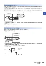
Digital output interface DO-1
This is a circuit in which the collector of the output transistor is the output terminal. When the output transistor is turned on, the
current flows to the collector terminal.
A lamp, relay, or photocoupler can be driven. Install a diode (D) for an inductive load, or install an inrush current suppressing
resistor (R) for a lamp load.
(Rated current: 40 mA or less, maximum current: 50 mA or less, inrush current: 100 mA or less) A maximum of 2.6 V voltage
drop occurs in the servo amplifier. The following connection diagram is for the sink output.
*1 If the voltage drop (a maximum of 2.6 V) interferes with the relay operation, apply high voltage (a maximum of 26.4 V) from an external
source.
*2 It is 500 mA for the MR-J5-_A_.
Refer to the following for the source output.
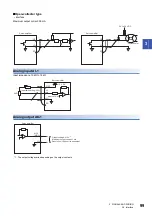
Pulse train input interface DI-2 [A]
Give a pulse train signal in the differential line driver type or open-collector type.
■
Differential line driver type
• Interface
*1 A photocoupler is used as the pulse train input interface. Therefore this circuit may not operate properly due to reduction in current if a
resistor is connected to the pulse train signal line.
*2 Set [Pr. PA13.2] to "0" to use the input pulse frequency of 4 Mpulses/s.
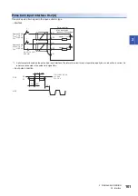
• Input pulse condition
ALM
DOCOM
300 mA
*2
± 10 %
*1
Servo amplifier
If polarity of diode is
reversed, servo amplifier
will malfunction.
Load
etc.
24 V DC
SD
PG (NG)
PP (NP)
V
OH
: 2.5 V
*1
V
OL
: 0.5 V
Servo amplifier
Max. input pulse
frequency 4 Mpulses/s
*2
10 m or less
Approx. 100
Ω
Am26LS31 or equivalent
0.9
0.1
tc
tLH
tc
tHL
tF
PP/PG
NP/NG
tLH = tHL < 50 ns
tc > 75 ns
tF > 3
μ
s
Summary of Contents for MELSERVO-J5 MR-J5-G Series
Page 2: ......
Page 473: ...12 USING A FULLY CLOSED LOOP SYSTEM 12 7 Absolute position detection system 471 12 MEMO ...
Page 477: ......


