3 SIGNALS AND WIRING
3.6 Interface
95
3
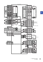
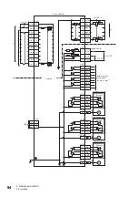
*1 Signals can be assigned to these pins with servo parameters ([Pr. PD03] to [Pr. PD05]).
*2 This diagram shows a sink I/O interface. For the source I/O interface, refer to the following.
*3 The diagram is for 3-axis servo amplifiers.
*4 In the initial setting, CINP (AND in-position) is assigned to this pin. The device of the pin can be changed with [Pr. PD08.0].
*5 This signal cannot be used on 3-axis servo amplifiers.
*6 Although the diagram shows the input signal and the output signal each using a separate 24 V DC power supply for illustrative purposes,
the system can be configured to use a single 24 V DC power supply.
Summary of Contents for MELSERVO-J5 MR-J5-G Series
Page 2: ......
Page 473: ...12 USING A FULLY CLOSED LOOP SYSTEM 12 7 Absolute position detection system 471 12 MEMO ...
Page 477: ......


