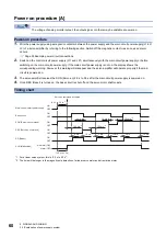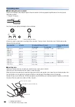
52
3 SIGNALS AND WIRING
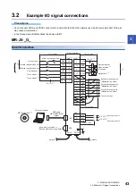
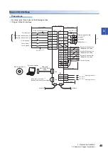
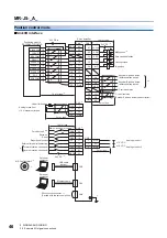
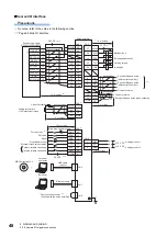
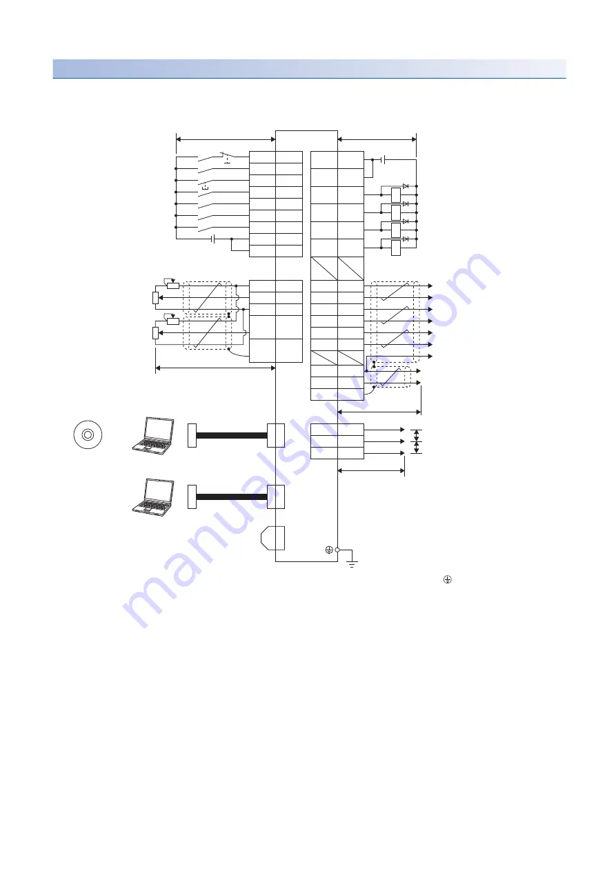
3.2 Example I/O signal connections
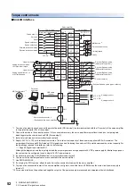
Torque control mode
■
Sink I/O interface
*1 To prevent an electric shock, connect the protective earth (PE) terminal (the terminal marked with the
symbol) of the servo amplifier
to the protective earth (PE) of the cabinet.
*2 Connect the diode in the correct direction. If it is connected reversely, the servo amplifier may malfunction and not output signals,
disabling protective circuits such as EM2 (Forced stop 2).
*3 Install a forced stop switch (normally closed contact).
*4 Supply 24 V DC ± 10 % to interfaces from outside. The total current capacity of these power supplies is 500 mA maximum. The
amperage will not exceed 500 mA when all I/O signals are used. Reducing the number of I/O points decreases the current capacity. For
the amperage required for interfaces, refer to the following.
Page 96 Digital input interface DI-1
Although the diagram shows the input signal and the output signal each using a separate 24 V DC power supply for illustrative purposes,
the system can be configured to use a single 24 V DC power supply.
*5 If no alarm is occurring, ALM (Malfunction) is on (normally closed contact).
*6 The pins with the same signal name are connected in the servo amplifier.
*7 Use SW1DNC-MRC2-_.
*8 If not using the STO function, attach the short-circuit connector that came with the servo amplifier.
*9 To prevent an unexpected restart of the servo amplifier, configure a circuit that turns off EM2 when the main circuit power supply is
turned off.
*10 For source interfaces, the positive and negative outputs of the power supply are reversed as compared with sink interfaces.
46
DOCOM
48
ALM
23
ZSP
25
VLC
49
RD
4
LA
5
LAR
6
LB
7
LBR
34
LG
33
OP
SD
CN3
*6
42
15
19
18
17
21
EM2
SON
RES
RS1
RS2
DICOM
CN3
*6
CN3
*6
1
27
SD
P15R
TC
LG
28
CN8
*1
MO1
MO2
3
LG
1
2
CN6
*2
RA2
RA3
RA4
RA1
47
DOCOM
8
LZ
9
LZR
41
SP1
16
SP2
20
DICOM
VLA
2
CN5
CN1
MR Configurator2
*7
+
Servo amplifier
10 m or less
10 m or less
Main circuit power supply
*9
24 V DC
*4
Forced stop 2
*3
Servo-on
Reset
Speed selection 1
Malfunction
*5
Speed selection 2
Zero speed detection
Forward rotation selection
Reverse rotation selection
Limiting speed
Ready
24 V DC
*4
Upper limit setting
Encoder Z-phase pulse
(differential line driver)
Analog torque command
+8 V/maximum torque
Encoder A-phase pulse
(differential line driver)
Upper limit setting
Analog speed limit 0 V to
±10 V/rated speed
Encoder B-phase pulse
(differential line driver)
Plate
Control common
2 m or less
Encoder Z-phase pulse (open collector)
Plate
2 m or less
Analog monitor 1
Analog monitor 2
2 m or less
Short-circuit connector
*8
(Packed with the servo amplifier)
USB cable
Personal
computer
Personal
computer
Ethernet cable
(option)
± 10 V DC
± 10 V DC
Summary of Contents for MELSERVO-J5 MR-J5-G Series
Page 2: ......
Page 473: ...12 USING A FULLY CLOSED LOOP SYSTEM 12 7 Absolute position detection system 471 12 MEMO ...
Page 477: ......


