226
6 OPTIONS AND PERIPHERAL EQUIPMENT
6.10 Molded-case circuit breakers, fuses, magnetic contactors
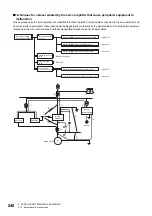
Main circuit wiring (connecting multiple servo amplifiers to one
molded-case circuit breaker)
When connecting multiple servo amplifiers to one molded-case circuit breaker for reasons such as the ease of installing a
molded-case circuit breaker (MCCB) into a cabinet or the cost efficiency, check that the following requirements are satisfied
before starting the servo system.
The number of servo amplifiers that can be connected to the molded-case circuit breaker is based on the wires to be
connected to the molded-case circuit breaker, and can be checked by referring to the operation characteristics of the molded-
case circuit breaker and the sum of the inrush currents of the servo amplifiers.
The check procedure is as follows.
1.
Selecting a wire (thickness)
When connecting multiple servo amplifiers, determine the wire thickness based on the total current, which is calculated by
multiplying the rated input currents of the servo amplifiers by the coefficient (125 %).
1.25 (125 %) is the coefficient based on UL 508A. For NFPA79, the coefficient is 1.15 (115 %). The coefficient varies
depending on the selection conditions and standards.
The permissible current for the wire (insulated conductor) varies depending on the usage conditions (ambient temperature,
number of wires bundled, and so on).
If the selection result is a wire that is too thick to be wired to the servo amplifier, multiple servo amplifiers cannot be connected
to one molded-case circuit breaker. Reduce the number of servo amplifiers until the wire size is acceptable for the servo
amplifier, or install a molded-case circuit breaker separately.
2.
Selecting a molded-case circuit breaker
Select a molded-case circuit breaker whose permissible current is equal to or less than the permissible current of the wire
selected in "Selecting a wire (thickness)".
Note that a molded-case circuit breaker whose rated current is greater than the permissible current of the wire cannot be
selected. Doing so may cause the wire to burn.
3.
Checking the number of servo amplifiers to connect to the molded-case circuit breaker
Check that the sum of the inrush currents of the servo amplifiers to be connected is equal to or smaller than six times the rated
current of the molded-case circuit breaker.
4.
Selecting a magnetic contactor (MC)
Select a magnetic contactor based on the permissible current for the selected wire.
Configure a system so that the magnetic contactor is shut off by an alarm output of the connected servo amplifiers.
Total current of multiple servo amplifiers [A] = 1.25
Servo amplifier k [A]
Summary of Contents for MELSERVO-J5 MR-J5-G Series
Page 2: ......
Page 473: ...12 USING A FULLY CLOSED LOOP SYSTEM 12 7 Absolute position detection system 471 12 MEMO ...
Page 477: ......

