3 SIGNALS AND WIRING
3.5 Signal (device) explanation
85
3
Input signal
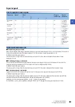
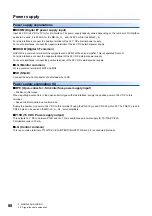
List of supported input signals
Input signal explanation [A]
■
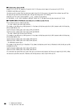
TLA (Analog torque limit)
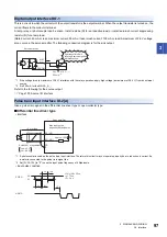
When TLA is enabled, all the torque generated by the servo motor is limited. Apply 0 V DC to +10 V DC between TLA and LG.
Connect the positive terminal of the power supply to TLA. The maximum torque is generated at +10 V.
MR-J5 User's Manual (Function)
If a value equal to or larger than the maximum torque is input to TLA, the value is clamped at the maximum torque.
Resolution: 12 bits
■
TC (Analog torque command)
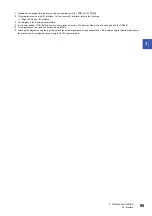
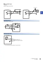
This is used to control all the torque generated by the servo motor. Apply 0 V DC to ±8 V DC between TC and LG. The
maximum torque is generated at ±8 V. The torque at ±8 V can be changed with [Pr. PC13].
MR-J5 User's Manual (Function)
If a value equal to or larger than the maximum torque is input to TC, the value is clamped at the maximum torque.
■
VC (Analog speed command)
Apply 0 V DC to ±10 V DC between VC and LG. At ±10 V, the servo motor speed is the value set in [Pr. PC12].
MR-J5 User's Manual (Function)
If a value equal to or larger than the maximum speed is input to VC, the value is clamped at the maximum speed. When
changing the speed to the permissible speed, change the setting value in [Pr. PA28.4].
Resolution: 14 bits or its equivalent (MR-J5-_A_-RJ_: 16 bits or its equivalent)
For the MR-J5-_A_-RJ_ servo amplifiers, setting [Pr. PC60.1] to "2" changes the analog input resolution to 14 bits.
Device name
Symbol
Model
I/O signal
interface type
Detailed
explanation
G
A
P
S
T
Analog torque
limit
TLA
AI-1
Analog torque
command
TC
AI-1
Analog speed
command
VC
AI-1
Analog speed
limit
VLA
AI-1
Forward/reverse
rotation pulse
train
PP/NP/PP2/NP2/
PG/NG
DI-2
Summary of Contents for MELSERVO-J5 MR-J5-G Series
Page 2: ......
Page 473: ...12 USING A FULLY CLOSED LOOP SYSTEM 12 7 Absolute position detection system 471 12 MEMO ...
Page 477: ......

