452
12 USING A FULLY CLOSED LOOP SYSTEM
12.3 Signals and wiring
12.3
Signals and wiring
• Be sure to use the load side encoder cables specified in this section. Using products other than those
specified may cause a malfunction.
• Contact the manufacturer of the load-side encoder being used for information on specifications,
performance, and guarantees.
Encoder cable configuration diagram
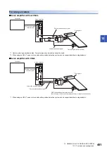
Configuration diagrams of the servo amplifier and load-side encoder are shown below. The cable to be used differs depending
on the load-side encoder.
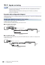
Encoder cable configuration diagram for linear encoders
For encoder cables for linear encoders, refer to the following manual.
MR-J5 Partner's Encoder User's Manual
The encoder cable to be used differs depending on the load-side encoder.
■
Servo amplifier without CN2L
■
Servo amplifier with CN2L
A linear encoder can be connected without using an MR-J4FCCBL03M branch cable. In addition, a four-wire type linear
encoder can also be used.
CN2
CN2
MOTOR
SCALE
Servo amplifier
Linear encoder
MR-J4FCCBL03M branch cable
Encoder of rotary servo motor
Encoder cable
Load-side
encoder
CN2
CN2L
Servo amplifier
Linear encoder
Encoder of rotary servo motor
Encoder cable
Load-side
encoder
Summary of Contents for MELSERVO-J5 MR-J5-G Series
Page 2: ......
Page 473: ...12 USING A FULLY CLOSED LOOP SYSTEM 12 7 Absolute position detection system 471 12 MEMO ...
Page 477: ......

