187
Selection of operation mode and
operation location
4
PA
R
A
M
E
T
E
R
S
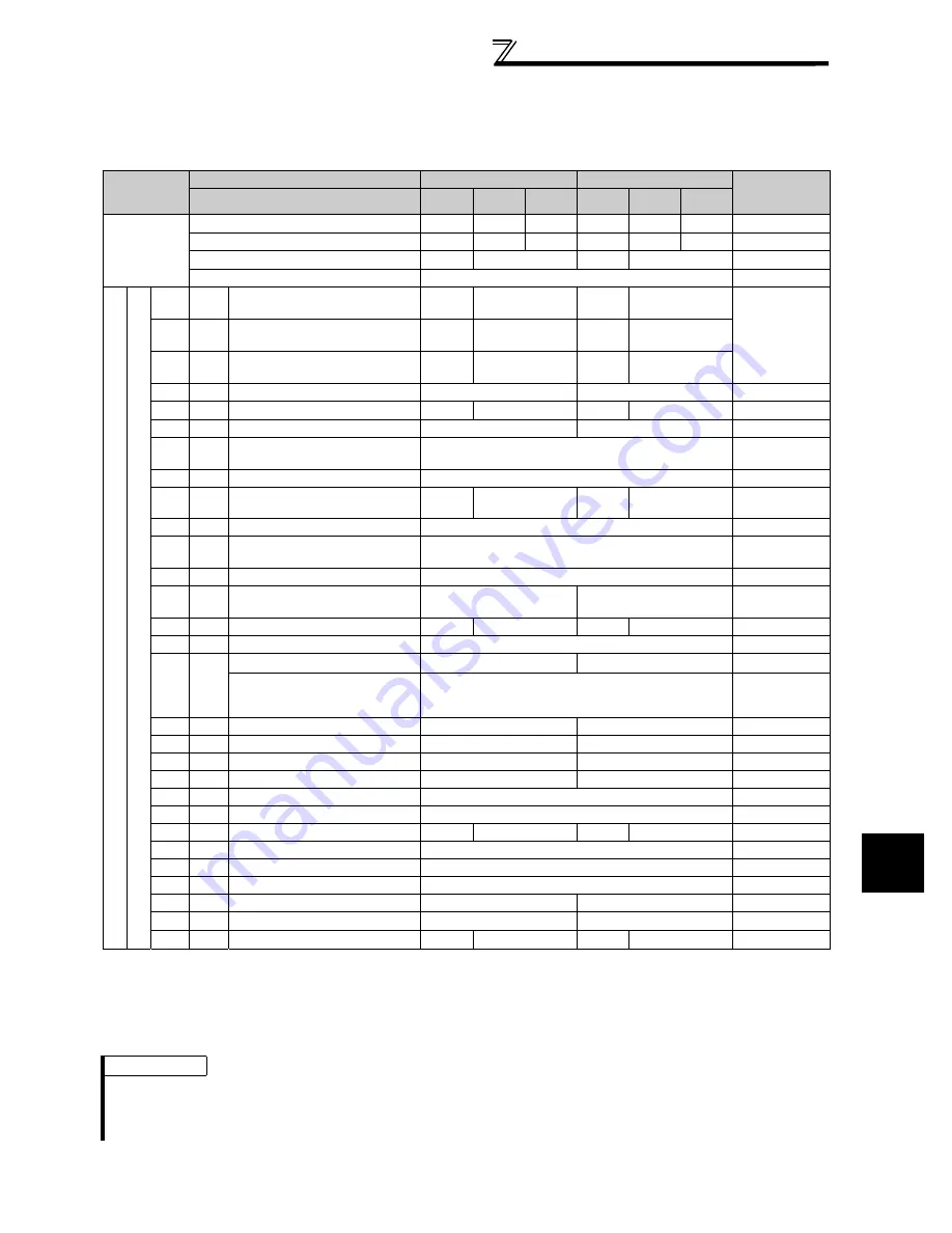
(5) Selection of command source in Network operation mode
(Pr. 338, Pr. 339)
There are two control sources: operation command source, which controls the signals related to the inverter start
command and function selection, and speed command source, which controls signals related to frequency setting.
In Network operation mode, the commands from the external terminals and communication (RS-485 terminals or
communication option) are as listed below.
[Explanation of table]
External
: Command only from control terminal signal is valid.
NET
: Command only from communication is valid
Combined
: Command from either of external terminal and communication is valid.
: Command from either of external terminal and communication is invalid.
Compensation : Command by signal from external terminal is only valid when
Pr. 28 Multi-speed input compensation selection
= "1"
Operation
Location
Selection
Pr. 338 Communication operation command source
0: NET
1: External
Remarks
Pr. 339 Communication speed command source
0: NET
1:External 2:External 0: NET
1:External 2:External
Fixed function
(Terminal-
equivalent
function)
Running frequency from communication
NET
NET
NET
NET
Terminal 2
External
External
Terminal 4
External
External
Terminal 1
Compensation
Sel
e
cti
ve
fu
n
c
ti
o
n
P
r.
17
8
to
P
r.
189
s
et
ting
0
RL
Low speed operation command/
remote setting clear
NET
External
NET
External
Pr. 59
= "0" (multi-
speeds)
Pr. 59
= "1 , 2"
(remote)
1
RM
Middle-speed operation command/
remote setting deceleration
NET
External
NET
External
2
RH
High speed operation command/
remote setting acceleration
NET
External
NET
External
3
RT
Second function selection
NET
External
4
AU
Terminal 4 input selection
Combined
Combined
5
JOG Jog operation selection
External
6
CS
Selection of automatic restart after
instantaneous power failure
External
7
OH
External thermal relay input
External
8
REX Fifteen speed selection
NET
External
NET
External
Pr. 59
= "0"
(multi-speeds)
10
X10 Inverter operation enable signal
External
11
X11
FR-HC or MT-HC connection,
instantaneous power failure detection
External
12
X12 PU operation external interlock
External
13
X13
External DC injection brake
operation is started
NET
External
14
X14 PID control valid terminal
NET
External
NET
External
16
X16 PU-external operation switchover
External
24
MRS
Output stop
Combined
External
Pr. 79
z
"7"
PU operation interlock
External
Pr. 79
= "7"
When X12 signal
is not assigned
25
STOP Start self-holding selection
External
37
X37 Traverse function selection
NET
External
60
STF Forward rotation command
NET
External
61
STR Reverse rotation command
NET
External
62
RES Reset
External
63
PTC PTC thermistor input
External
64
X64 PID forward action switchover
NET
External
NET
External
65
X65 PU-NET operation switchover
External
66
X66 External-NET operation switchover
External
67
X67 Command source switchover
External
70
X70 DC feeding operation permission
NET
External
71
X71 DC feeding cancel
NET
External
72
X72 PID integral value reset
NET
External
NET
External
REMARKS
The command source of communication is as set in
Pr. 550
and
Pr. 551
.
The
Pr. 338
and
Pr. 339
settings can be changed while the inverter is running when
Pr. 77
= "2". Note that the setting change is
reflected after the inverter has stopped. Until the inverter has stopped, communication operation command source and
communication speed command source before the setting change are valid.
Summary of Contents for F700
Page 327: ...318 MEMO ...
Page 340: ...331 MEMO ...


