background image

Chapter 7    Home Networking

94

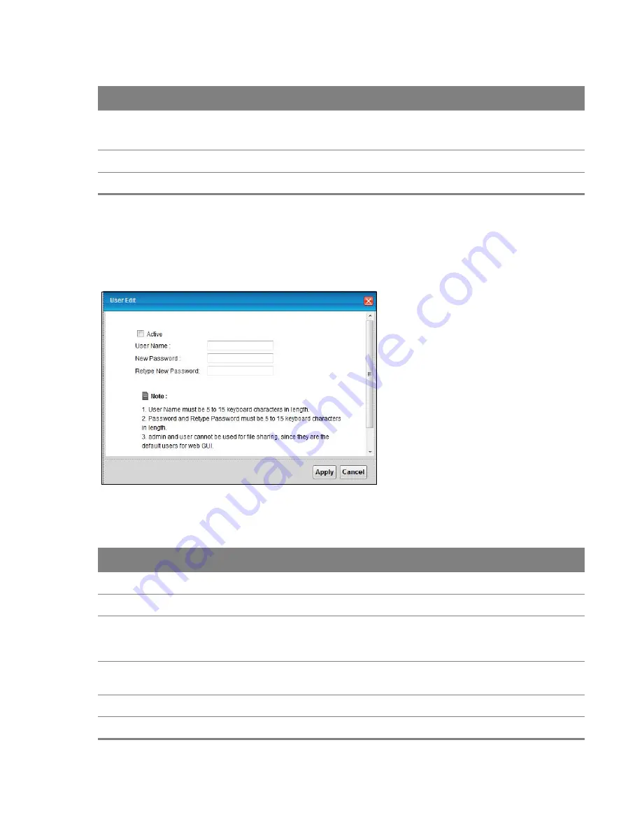
7.7.2  Edit File Sharing User

Use this screen to edit a file sharing user on the Device. Click the 

Edit

 icon next to a user account.

Figure 51 

File Sharing: Add/Edit

Each field is described in the following table.

Table 32   

File Sharing: Add/Edit 

LABEL

DESCRIPTION

Active

Select this to activate the file sharing user account.

User Name

Type the user name for the account.

New Password

Type your new system password (up to 30 characters). Note that as you type a 

password, the screen displays a (*) for each character you type. After you change the 

password, use the new password to access the Device.

Retype New 

Password

Type the new password again for confirmation.

Apply

Click 

Apply

 to save your changes.

Cancel

Click 

Cancel

 to exit this screen without saving.

Modify

Click the 

Edit

 icon to configure a file sharing user account’s settings.

Click the 

Delete

 icon to delete this user account from the list.

Apply

Click 

Apply

 to save your changes.

Cancel

Click 

Cancel

 to restore your previously saved settings.

Table 31   

Network Setting > Home Networking > File Sharing (continued)

LABEL

DESCRIPTION

Summary of Contents for DSL-100HNU-T1 v3

Page 1: ...014 MitraStar Technology Corp Firmware Version 1 14 Edition 1 12 2014 Default Login Details http 192 168 1 1 User Name admin Password 1234 DSL 100HNU T1 v3 802 11n 2x2 Wireless ADSL2 4 port Gateway Us...

Page 2: ...to differences in operating systems operating system versions or if you installed updated firmware software for your device Every effort has been made to ensure that the information in this manual is...

Page 3: ...5 Overview 15 Accessing the Web Configurator 17 The Web Configurator Layout 17 Title Bar 18 Main Window 19 Chapter 3 Quick Start 19 Overview 19 Quick Start Setup 22 Chapter 4 Connection Status and Sys...

Page 4: ...ion 56 More Secure WPA2 PSK 57 WPA2 Authentication 59 More AP Screen 60 Edit More AP 61 MAC Authentication Screen 63 The WPS Screen 65 The WDS Screen 67 The WMM Screen 68 Scheduling Screen 69 Add or E...

Page 5: ...c Route Edit 112 Chapter 9 Quality of Service QoS 112 Overview 112 What You Can Do in this Chapter 112 What You Need to Know 113 The QoS General Screen 114 The Queue Setup Screen 115 Edit a QoS Queue...

Page 6: ...Screens 146 The IP MAC Filter Screen 148 The IPv6 MAC Filter Screen 151 Chapter 14 Firewall 151 Overview 151 What You Can Do in the Firewall Screens 152 What You Need to Know About Firewall 153 Firewa...

Page 7: ...or 181 Overview 181 What You Can Do in this Chapter 181 What You Need To Know 182 The Log Screen 183 The WAN Traffic Status Screen 184 The LAN Traffic Status Screen 185 The NAT Traffic Status Screen 1...

Page 8: ...WW Screen 205 Configuring the WWW Screen 206 Telnet Screen 207 FTP Screen 208 SNMP Screen 209 Configuring SNMP 210 DNS Screen 211 ICMP Screen 212 SSH Screen 213 SSH Example 216 Chapter 26 Diagnostic 2...

Page 9: ...ia a 3G wireless card or share files via a USB memory stick or a USB hard drive The Device can also function as a print server with an USB printer connected Only use firmware for your Device s specifi...

Page 10: ...ice s LAN ports or wirelessly Figure 1 Device s Router Features DSL LAN Configure firewall and filtering features on the Device for secure Internet access Set the firewall to allow responses from the...

Page 11: ...button Figure 2 Wireless Access Example 1 5 1 Using the WLAN WPS Button By default the Device s wireless network is enabled To turn it off simply press the WPS WLAN button on top of the Device for ov...

Page 12: ...the RESET button at the back of the device to reload the factory default configuration file This means that you will lose all configurations that you had previously and the user name and password wil...

Page 13: ...ng with other wireless clients Orange Blinking The Device is setting up a WPS connection Off The wireless network is not activated DSL Green On The DSL line is up Blinking The DSL line is initializing...

Page 14: ...Chapter 1 Introduction 14...

Page 15: ...eb configurator you need to allow Web browser pop up windows from your device Web pop up blocking is enabled by default in Windows XP SP Service Pack 2 JavaScript enabled by default Java permissions e...

Page 16: ...gain 5 The following screen displays if you have not yet changed your password It is strongly recommended you change the default password Enter a new password retype it to confirm and click Apply alte...

Page 17: ...information 2 2 The Web Configurator Layout Click Connection Status System Info to show the following screen Figure 7 Web Configurator Layout B C A a b As illustrated above the main screen is divided...

Page 18: ...est of this document Click LAN Device on the System Info screen a in Figure 7 on page 17 to display the Connection Status screen See Chapter 4 on page 24 for more information on the System Info and Co...

Page 19: ...eless settings See the rest of this guide for background information on the features in this chapter 3 2 Quick Start Setup 1 The Quick Start Wizard appears automatically after login Or you can click t...

Page 20: ...r 3 Quick Start 20 2 Enter your Internet connection information in this screen The screen and fields to enter may vary depending on your current connection type Click Next Figure 10 WAN Interface Sele...

Page 21: ...LAN on or off If you keep it on record the security settings so you can configure your wireless clients to connect to the Device Click Save Figure 11 Internet Connection 4 Your Device saves your sett...

Page 22: ...rfaces LAN WAN and WLAN and SIP accounts You can also register and unregister SIP accounts If you click Virtual Device on the System Info screen a visual graphic appears showing the connection status...

Page 23: ...cted LAN devices in a list click List View in the Viewing mode selection box Figure 13 Connection Status List View In Icon View if you want to view information about a client click the client s name a...

Page 24: ...field is described in the following table Table 2 System Info Screen LABEL DESCRIPTION Refresh Interval Select how often you want the Device to update this screen from the drop down list box Device In...

Page 25: ...ws the first and second DNS server address assigned by the ISP LAN Information IP Address This field displays the current IP address of the Device in the LAN IP Subnet Mask This field displays the cur...

Page 26: ...iFi interface Security Firewall This shows whether or not the firewall is enabled on System Status DSL UpTime This field displays how long the DSL connection has been active System Uptime This field d...

Page 27: ...Interface This column displays each interface the Device has Status This field indicates whether or not the Device is using the interface For the LAN interfaces this field displays Up when the Device...

Page 28: ...t connects your private networks such as a LAN Local Area Network and other networks so that a computer in one location can communicate with computers in other locations Figure 15 LAN and WAN WAN LAN...

Page 29: ...address to connect to the Internet and communicate with devices in other networks It can be static fixed or dynamically assigned by the ISP when the Device connects to the Internet If your ISP assigns...

Page 30: ...to the ISP s Border Relay router BR in the figure to connect to the native IPv6 Internet The local network can also use IPv4 services The Device uses it s configured IPv4 WAN IP to route IPv4 traffic...

Page 31: ...LAN IPv6 IPv4 WAN IPv6 IPv4 in IPv6 Dual Stack Lite 3G 3G Third Generation is a digital packet switched wireless technology Bandwidth usage is optimized as multiple users share the same channel and b...

Page 32: ...Connection Screen Use this screen to change your Device s WAN settings Click Network Setting Broadband Internet Connection The screen differs by the mode and encapsulation you select Figure 19 Networ...

Page 33: ...ssigned If assigned a name in the form user domain where domain identifies a service name then enter both components exactly as given Password PPPoA and PPPoE encapsulation only Enter the password ass...

Page 34: ...tunneling relay server s IPv4 address in this field Via DHCP Option 212 Select this to have the Device detect it automatically through DHCP option 212 Manual Select this to manually enter the followin...

Page 35: ...ct it automatically through DHCPv6 Remote IPv6 Address When you set the Mode field to Manual specify the AFTR IPv6 address IPv6 Address When you enable Static IP Address enter the IPv6 address of the...

Page 36: ...t on Demand Select Connect on Demand when you don t want the connection up all the time and specify an idle time out in the Max Idle Timeout field Max Idle Time Specify an idle time out in the Max Idl...

Page 37: ...duce multicast traffic significantly Select None to turn off MLD proxy ATM QoS This section is available when the connection s Virtual Channel field is set to an ADSL option ATM QoS Type Select CBR Co...

Page 38: ...onnection Enter the MTU in this field For ENET ENCAP the MTU value is 1500 For PPPoE the MTU value is 1492 For PPPoA and RFC 1483 the MTU is 65535 Apply Click this to save your changes Cancel Click th...

Page 39: ...and multiplexing type the Internet connection uses Modify The first ISP connection is read only in this screen Use the Broadband Internet Connection screen to edit it Click the Edit icon to edit the I...

Page 40: ...multiplexing used by your ISP from the drop down list Choices are VC Mux or LLC By prior agreement a protocol is assigned a specific virtual circuit for example VC1 will carry IP If you select VC mux...

Page 41: ...v6 prefix from the connected router s Router Advertisement RA to generate an IPv6 address Static IP Address Select this option if you have a fixed IPv6 address assigned by your ISP DHCP IPv6 Select DH...

Page 42: ...Idle Timeout field Max Idle Timeout Specify an idle time out in the Max Idle Timeout field when you select Connect on Demand The default setting of 0 means the Internet session will not timeout NAT If...

Page 43: ...m None Both In Only and Out Only RIP Version You do not configure this field if you set the RIP Direction field to None Select the RIP Version from RIP 1 RIP 2B RIP 2M Multicast Devices use the IGMP I...

Page 44: ...ain Cell Rate SCR sets the average cell rate long term that can be transmitted Type the SCR which must be less than the PCR Note the system default of 0 cells sec Maximum Burst Size Maximum Burst Size...

Page 45: ...8 Network Setting Broadband 3G Backup LABEL DESCRIPTION 3G Backup Select Enable 3G Backup to have the Device use the 3G connection as your WAN or a backup when the wired WAN connection fails Card Desc...

Page 46: ...ss Automatically Select this option If your ISP did not assign you a fixed IP address Use the following static IP address Select this option If the ISP assigned a fixed IP address IP Address Enter you...

Page 47: ...g PPPoE For the service provider PPPoE offers an access and authentication method that works with existing access control systems for example RADIUS PPPoE lets you access one of multiple network servi...

Page 48: ...ing overhead this method may be advantageous if it is not practical to have a separate VC for each carried protocol for example if charging heavily depends on the number of simultaneous VCs 5 5 3 VPI...

Page 49: ...dynamic IP For a static IP you must fill in all the IP Address and Gateway IP Address fields as supplied by your ISP However for a dynamic IP the Device acts as a DHCP client on the WAN port and so th...

Page 50: ...the Device acts as a bridge with other access points Use the WMM screen to enable Wi Fi MultiMedia WMM to ensure quality of service in wireless networks for multimedia applications Section 6 7 on pag...

Page 51: ...work is the part in the blue circle In this wireless network devices A and B use the access point AP to interact with the other devices such as the printer or with the Internet Your Device is the AP E...

Page 52: ...le What is the most appropriate standard to use What security options do the other wireless devices support WPA2 PSK for example What is the best one to use Do the other wireless devices support WPS W...

Page 53: ...OFF button to ON to use wireless LAN The WLAN LED should be on Wireless Network Settings Wireless Network Name SSID The SSID Service Set IDentity identifies the service set with which a wireless devic...

Page 54: ...l that is as many channels away from any channels used by neighboring APs as possible The channel number which the Device is currently using then displays in the Operating Channel field Scan Click thi...

Page 55: ...emented for ease of use and when security is not an issue The wireless station and the AP or peer computer do not share a secret key Thus the wireless stations can associate with any AP or peer comput...

Page 56: ...SCII characters or 10 hexadecimal characters 0 9 A F If you chose 128 bit WEP then enter 13 ASCII characters or 26 hexadecimal characters 0 9 A F WEP Encryption Select 64 bits or 128 bits This dictate...

Page 57: ...ice supports WPA PSK and WPA2 PSK simultaneously Group Key Update Timer The Group Key Update Timer is the rate at which the RADIUS server sends a new group key out to all clients Encryption If the sec...

Page 58: ...IP Address Enter the IP address of the external authentication server in dotted decimal notation Port Number Enter the port number of the external authentication server The default port number is 181...

Page 59: ...reauthentication off Note If wireless station authentication is done using a RADIUS server the reauthentication timer on the RADIUS server has priority WPA Compatible Select this if you want the Devic...

Page 60: ...BSSs The SSID Service Set IDentifier identifies the Service Set with which a wireless device is associated This field displays the name of the wireless profile on the network When a wireless client sc...

Page 61: ...elect both Client Isolation and MBSSID LAN Isolation to allow this SSID s wireless clients to only connect to the Internet through the Device Security Level Security Mode Select Basic WEP or More Secu...

Page 62: ...table Select Disable to turn off MAC filtering Select Deny to block access to the Device MAC addresses not listed will be allowed to access the Device Select Allow to permit access to the Device MAC...

Page 63: ...ies the security settings of the SSID1 profile see Section 6 2 on page 52 If you want to use the WPS feature make sure you have set the security mode of SSID1 to WPA2 PSK or WPA2 PSK WPA PSK mixed or...

Page 64: ...ck Apply to activate WPS on the Device Add a new device with WPS Method These fields display after you enable WPS and click Apply Method 1 PBC Use this section to set up a WPS wireless network using P...

Page 65: ...ry when you use WPS push button method Click the Generate New PIN button to have the Device create a new PIN Status This displays Configured when the Device has connected to a wireless network using W...

Page 66: ...ect the type of the key used to encrypt data between APs All the wireless APs including the Device must use the same pre shared key for data transmission The option is available only when you set the...

Page 67: ...SCRIPTION Enable WMM of SSID1 4 This enables the Device to automatically give a service a priority level according to the ToS value in the IP header of packets it sends WMM QoS Wifi MultiMedia Quality...

Page 68: ...eate a new wireless LAN scheduling rule This is the index number of the entry Rule Name This field shows the name configured for the scheduling rule Days This field displays to which days of the week...

Page 69: ...Scheduling Add New Rule LABEL DESCRIPTION From Schedule Rules To create a new scheduling rule based off an existing one select it here Rule Name Specify a descriptive name to identify the scheduling...

Page 70: ...o associate with the Device Select 802 11g to allow only IEEE 802 11g compliant WLAN devices to associate with the Device Select 802 11b g to allow either IEEE 802 11b or IEEE 802 11g compliant WLAN d...

Page 71: ...ming in your wireless network There are two preamble modes long and short If a device uses a different preamble mode than the Device does it cannot communicate with the Device Authentication The proce...

Page 72: ...security standard is very secure if you use a long key which is difficult for an attacker s software to guess for example a twenty letter long string of apparently random numbers and letters but it i...

Page 73: ...like a secret code If you do not know the secret code you cannot understand the message The types of encryption you can choose depend on the type of authentication See Section 6 10 2 2 on page 73 for...

Page 74: ...se wireless networks are radio networks their signals are subject to limitations of distance interference and absorption Problems with distance occur when the two radios are too far apart Problems wit...

Page 75: ...is also the possibility of channel interference The Device s MBSSID Multiple Basic Service Set IDentifier function allows you to use one access point to provide several BSSs simultaneously You can the...

Page 76: ...At the time of writing WDS security is not compatible with all access points Refer to your other access point s documentation for details The following figure illustrates how WDS link works between AP...

Page 77: ...e Static DHCP screen to assign IP addresses on the LAN to specific individual computers based on their MAC Addresses Section 7 3 on page 82 Use the IP Alias screen Section 7 4 on page 84 to configure...

Page 78: ...es you enter when you set up DHCP are passed to the client machines along with the assigned IP address and subnet mask 7 1 2 2 About UPnP How do I know if I m using UPnP UPnP hardware is identified as...

Page 79: ...ing systems such as Windows or Linux have different file systems The file sharing feature on your Device supports FAT16 FAT32 NTFS EXT2 and EXT3 Common Internet File System The Device uses Common Inte...

Page 80: ...for printing and be compatible with the RAW port 9100 protocol The following OSs support Device s printer sharing feature Microsoft Windows 95 Windows 98 SE Second Edition Windows Me Windows NT 4 0 Wi...

Page 81: ...nds and receives on the subnet Select the RIP Direction from None Both IN Only and OUT Only Multicast IGMP Internet Group Multicast Protocol is a network layer protocol used to establish membership in...

Page 82: ...ult The Device sends out its own LAN IP address to the DHCP clients as the first DNS server address DHCP clients use this first DNS server to send domain name queries to the Device The Device sends a...

Page 83: ...dwired address that is assigned at the factory This address follows an industry standard that ensures no other adapter has a similar address IP Address This field displays the IP address relative to t...

Page 84: ...ernet interface with the Device itself as the gateway for the LAN network When you use IP alias you can also configure firewall rules to control access to the LAN s logical network subnet Use this scr...

Page 85: ...Setting Home Networking Static DHCP UPnP to display the screen shown next Figure 47 Network Setting Home Networking UPnP The following table describes the labels in this screen Table 29 Network Settin...

Page 86: ...Chapter 7 Home Networking 86 7 6 The IPv6 LAN Setup Screen Use this screen to configure the IPv6 settings for your Device s LAN interface...

Page 87: ...Chapter 7 Home Networking 87 Figure 48 Network Setting Home Networking IPv6 LAN Setup...

Page 88: ...Identifier is appended to the IPv6 address prefix to create the routable global IPv6 address Select EUI64 to use the EUI 64 format to generate an interface ID from the Ethernet MAC address Lan Identi...

Page 89: ...formation to the clients Stateless The Device uses IPv6 stateless autoconfiguration RADVD Router Advertisement Daemon is enabled to have the Device send IPv6 prefix information in router advertisement...

Page 90: ...nor communicate with other networks if you disable this feature Delegate M O flag from WAN Select this to have the Device obtain the M O Managed Other flag setting from the service provider or uplink...

Page 91: ...retransmissions Possible values for this field are 1000 4294967295 RA Interval Enter the time in seconds between router advertisement messages Possible values for this field are 4 1800 Delegate MTU fr...

Page 92: ...oup In this case contact your network administrator 7 7 1 Before You Begin Make sure the Device is connected to your network and turned on 1 Connect the USB device to one of the Device s USB ports Mak...

Page 93: ...uration File Sharing Services SMB Select Enable to activate file sharing through the Device Share Directory Access Level Select Public to allow all LAN users to access the shared folders Select Securi...

Page 94: ...racters Note that as you type a password the screen displays a for each character you type After you change the password use the new password to access the Device Retype New Password Type the new pass...

Page 95: ...be connected to your Device A USB printer with the driver already installed on your computer The computers on your network must have the printer software already installed before they can create a TC...

Page 96: ...e The actual physical connection determines whether the Device ports are LAN or WAN ports There are two separate IP networks one inside the LAN network and the other outside the WAN network as shown n...

Page 97: ...ssigned Number Authority IANA reserved this block of addresses specifically for private use please do not use any other number unless you are told otherwise Let s say you select 192 168 1 0 as the net...

Page 98: ...ation do not create an arbitrary IP address always follow the guidelines above For more information on address assignment please refer to RFC 1597 Address Allocation for Private Internets and RFC 1466...

Page 99: ...lick OK to go back to the Add Remove Programs Properties window and click Next 5 Restart the computer when prompted Installing UPnP in Windows XP Follow the steps below to install the UPnP in Windows...

Page 100: ...Networking 100 4 The Windows Optional Networking Components Wizard window displays Select Networking Service in the Components selection box and click Details Figure 58 Windows Optional Networking Com...

Page 101: ...11 Using UPnP in Windows XP Example This section shows you how to use the UPnP feature in Windows XP You must already have UPnP installed in Windows XP and UPnP activated on the Device Make sure the...

Page 102: ...ight click the icon and select Properties Figure 60 Network Connections 3 In the Internet Connection Properties window click Settings to see the port mappings there were automatically created Figure 6...

Page 103: ...click Add to manually add port mappings Figure 62 Internet Connection Properties Advanced Settings Figure 63 Internet Connection Properties Advanced Settings Add 5 When the UPnP enabled device is disc...

Page 104: ...rrent Internet connection status Figure 65 Internet Connection Status Web Configurator Easy Access With UPnP you can access the web based configurator on the Device without finding out the IP address...

Page 105: ...es Figure 66 Network Connections 4 An icon with the description for each UPnP enabled device displays under Local Network 5 Right click on the icon for your Device and select Invoke The web configurat...

Page 106: ...Networking 106 6 Right click on the icon for your Device and select Properties A properties window displays with basic information about the Device Figure 68 Network Connections My Network Places Prop...

Page 107: ...s most traffic from A to the Internet through the Device s default gateway R1 You create one static route to connect to services offered by your ISP behind router R2 You create another static route to...

Page 108: ...rameter specifies the IP network address of the final destination Routing is always based on network number Gateway This is the IP address of the gateway The gateway is a router or switch on the same...

Page 109: ...bnet mask here Gateway IP Address You can decide if you want to forward packets to a gateway IP address or a bound interface If you want to configure Gateway IP Address enter the IP address of the nex...

Page 110: ...ion Routing is always based on network number Prefix length An IPv6 prefix length specifies how many most significant bits starting from the left in the address compose the network address This field...

Page 111: ...to specify a route to a single host use a prefix length of 128 in the prefix length field to force the network number to be identical to the host ID IPv6 Prefix Length Enter the address prefix to spec...

Page 112: ...lowing time sensitive applications to flow more smoothly Time sensitive applications include both those that require a low level of latency delay and a low level of jitter variations in delay such as...

Page 113: ...ew DS field which replaces the eight bit ToS Type of Service field in the IP header Tagging and Marking In a QoS class you can configure whether to add or change the DSCP DiffServ Code Point value ain...

Page 114: ...ccording to your classification rules Traffic which does not match any of the classification rules is mapped into the default queue with the lowest priority Ethernet Priority Automatically assign prio...

Page 115: ...name of this queue Interface This shows the name of the Device s interface through which traffic in this queue passes Priority This shows the priority of this queue Weight This shows the weight of thi...

Page 116: ...eights Rate Limit Specify the maximum transmission rate in Kbps or allowed for traffic on this queue OK Click this to save your changes Cancel Click this to exit this screen without saving 9 4 The Cla...

Page 117: ...oming in through a specific interface it displays here Classification Criteria This shows criteria specified in this classifier for example the interface from which traffic of this class should come a...

Page 118: ...ter 9 Quality of Service QoS 118 9 4 1 Add Edit QoS Class Click Add new Classifier in the Class Setup screen or the Edit icon next to an existing classifier to configure it Figure 78 Class Setup Add E...

Page 119: ...s means any source IP address IP Subnet Mask Enter the source subnet mask Exclude Select this option to exclude the packets that match the specified criteria from this classifier Port Range If you sel...

Page 120: ...t the service classification of the traffic FTP or SIP IP Protocol Select this option and select the protocol service type from TCP or UDP If you select User defined enter the protocol service type nu...

Page 121: ...class according to the default routing table If traffic of this class comes from a WAN interface and is in a queue that forwards traffic through the LAN WLAN interface the Device ignores the setting...

Page 122: ...N ID fields If you select Same the Device keep the Ethernet Priority and VLAN ID in the packets To configure the Ethernet Priority you can either select a priority number in the first drop down list b...

Page 123: ...These are the rates and burst sizes against which the policer checks the traffic of the member QoS classes Action This shows the how the policer has the Device treat different types of traffic belongi...

Page 124: ...urst size two rate three color or excess burst size single rate three color if it is also configured This is the maximum size of the first token bucket in a traffic metering algorithm Conforming Actio...

Page 125: ...about the topics covered in this chapter 9 7 1 DiffServ QoS is used to prioritize source to destination traffic flows All packets in the flow are given the same priority You can use CoS class of servi...

Page 126: ...S field DSCP is backward compatible with the three precedence bits in the ToS octet so that non DiffServ compliant ToS enabled network device will not conflict with the DSCP mapping DSCP 6 bits Unused...

Page 127: ...1 2 What You Need To Know The following terms and concepts may help as you read this chapter Inside Outside and Global Local Inside outside denotes where a host is located relative to the Device for e...

Page 128: ...en Figure 82 Network Setting NAT General The following table describes the fields in this screen Table 46 Network Setting NAT General LABEL DESCRIPTION Max NAT Firewall Session Per User Use this field...

Page 129: ...ocesses such as a Web or FTP server from your location Your ISP may periodically check for servers and may suspend your account if it discovers any active services at your location If you are unsure r...

Page 130: ...d if you manually added a service You can change this by clicking the edit icon External Start Port This is the first external port number that identifies a service External End Port This is the last...

Page 131: ...is for a user defined entry Enter the original destination port for the packets To forward only one port enter the port number again in the External End Port field To forward a series of ports enter t...

Page 132: ...n the Port Forwarding screen Note If you do not assign a default server the Device discards all packets received for ports not specified in the virtual server configuration Apply Click this to save yo...

Page 133: ...NAT ALG LABEL DESCRIPTION SIP ALG Enable this to make sure SIP VoIP works correctly with port forwarding Apply Click this to save your changes back to the Device Cancel Click Cancel to restore your p...

Page 134: ...st 10 6 2 What NAT Does In the simplest form NAT changes the source IP address in a packet received from a subscriber the inside local address to another the inside global address before forwarding th...

Page 135: ...nication with hosts on other networks It replaces the original IP source address and TCP or UDP source port numbers for Many to One and Many to Many Overload NAT mapping in each packet and then forwar...

Page 136: ...ersa For ports not belonging to a port binding group the Device forwards traffic according to the routing table Additionally specify ATM QoS settings for an ADSL virtual channel PVC to satisfy the ban...

Page 137: ...for the port binding group When a port is assigned to a port binding group traffic will be forwarded to the other ports in the group but not to ports in other groups If a port is not included in any...

Page 138: ...the labels in this screen Table 53 Network Setting Port Binding Port Binding Summary LABEL DESCRIPTION Group ID This field displays the group index number Group Port This field displays the ports and...

Page 139: ...ervice LABEL DESCRIPTION Index This is the index number for the port binding group Option60 This is the Vendor Class Identifier of the matched traffic Option61 This is the device identity of the match...

Page 140: ...llowing screen Figure 93 Any Port Any Service Add Edit The following table describes the labels in this screen Table 55 Any Port Any Service Add Edit LABEL DESCRIPTION Interface Select the WAN interfa...

Page 141: ...type Select DUID LLT DUID Based on Link layer Address Plus Time to enter the hardware type a time value and the MAC address of the device Select DUID EN DUID Assigned by Vendor Based upon Enterprise N...

Page 142: ...een and click Apply It is suggested to reboot the Device after you have changed the port binding settings or WAN encapsulation Figure 94 Network Setting Port Binding Disable OK Click this to save your...

Page 143: ...changes each time you reconnect Your friends or relatives will always be able to call you even if they don t know your IP address First of all you need to have registered a dynamic DNS account with ww...

Page 144: ...ynamic DNS service provider Host Name Type the domain name assigned to your Device by your Dynamic DNS provider Username Type your user name for the Dynamic DNS service provider Password Type your pas...

Page 145: ...rules you can configure to restrict traffic by IPv4 and IPv6 addresses and MAC addresses 13 1 1 What You Can Do in the Filter Screens Use the IP MAC Filter screen Section 13 2 on page 146 to create IP...

Page 146: ...ls in this screen Table 57 Security Filter LABEL DESCRIPTION Rule Type Rule Type selection Select White List to create a filter rule that allows traffic Select Black List to create a filter rule that...

Page 147: ...pper layer protocol Source MAC Address This field is only available when you select MAC in the Rule Type field Enter the MAC address of the packets you wish to filter IP MAC Filter Listing This is the...

Page 148: ...Security Filter IPv6 MAC Filter LABEL DESCRIPTION Rule Type Rule Type selection Select White List to create a filter rule that allows traffic Select Black List to create a filter rule that blocks traf...

Page 149: ...reachable 4 port unreachable 2 Packet Too Big 3 Time Exceeded 0 hop limit exceeded in transit 1 fragment reassembly time exceeded 4 Parameter Problem 0 erroneous header field encountered 1 unrecognize...

Page 150: ...PrefixLength This displays the source IPv6 address and prefix length Dest IP PrefixLength This displays the destination IPv6 address and prefix length Mac Address This is the MAC address of the packet...

Page 151: ...DDOS LAND and Ping of Death attacks whether the firewall is enabled or disabled The following figure illustrates the firewall action User A can initiate an IM Instant Messaging session from the LAN to...

Page 152: ...o the Internet Their goal is not to steal information but to disable a device or network so users no longer have access to network resources The Device is pre configured to automatically detect and th...

Page 153: ...from being sent This keeps outsiders from discovering your Device when unsupported ports are probed ICMP Internet Control Message Protocol ICMP is a message control and error reporting protocol betwee...

Page 154: ...This setting allows the customer to create and edit individual firewall rules Firewall rules can be created in the Default Action screen Section 14 3 on page 154 and Rules screen Section 14 4 on page...

Page 155: ...cted direction and do not match any of the firewall rules Select Drop to silently discard the packets without sending a TCP reset packet or an ICMP destination unreachable message to the sender Select...

Page 156: ...e the rule Source IP Address This column displays the source addresses or ranges of addresses to which this firewall rule applies Please note that a blank source or destination address is equivalent t...

Page 157: ...this screen to configure firewall rules In the Rules screen select an index number and click Add or click a rule s Edit icon to display this screen and refer to the following table for information on...

Page 158: ...hat includes Single Address Range Address Subnet Address and Any Address Start IP Address Enter the single IP address or the starting IP address in a range here End IP Address Enter the ending IP addr...

Page 159: ...en Edit Customized Services Click the Edit Customized Service button to bring up the screen that you use to configure a new custom service that is not in the predefined list of services TCP Flag Speci...

Page 160: ...tart Port This is a single port number or the starting port number of a range that defines your customized service End Port This is a single port number or the ending port number of a range that defin...

Page 161: ...hresholds at which the Device will start dropping sessions 14 5 1 The DoS Advanced Screen For DoS attacks the Device uses thresholds to determine when to start dropping sessions that do not become ful...

Page 162: ...d settings as the default threshold values should work for most small offices Tune these parameters when you believe the Device has been receiving DoS attacks that are not recorded in the logs or the...

Page 163: ...sions When the rate of new connection attempts rises above this number the Device deletes half open sessions as required to accommodate new connection attempts ICMP Echo Request Count This is the rate...

Page 164: ...teful packet inspection allows packets traveling in the following directions LAN to Router These rules specify which computers on the LAN can manage the Device remote management You can also configure...

Page 165: ...ncing Security With Your Firewall 1 Change the default password via web configurator 2 Think about access control before you connect to the network in any way 3 Limit who can access your router 4 Don...

Page 166: ...Triangle Route When the firewall is on your Device acts as a secure gateway between your LAN and the Internet In an ideal network topology all incoming and outgoing network traffic passes through the...

Page 167: ...our network into logical sections over the same Ethernet interface Your Device supports up to three logical LAN interfaces with the Device being the gateway for each logical network It s like having m...

Page 168: ...Chapter 14 Firewall 168 4 The Device then sends it to the computer on the LAN in Subnet 1 Figure 110 IP Alias 1 2 3 LAN A ISP 1 ISP 2 4 WAN Subnet 1 Subnet 2...

Page 169: ...ules Click Security Parental Control to open the following screen Figure 111 Security Parental Control The following table describes the fields in this screen Table 67 Parental Control Parental Contro...

Page 170: ...s configured If not None will be shown Website Blocked This shows whether the website block is configured If not None will be shown Modify Click the Edit icon to go to the screen where you can edit th...

Page 171: ...it it Use this screen to configure a restricted access schedule and or URL filtering settings to block the users on your network from accessing certain web sites Figure 112 Add Edit Parental Control R...

Page 172: ...viewing the Web sites with the URLs listed below If you select Access the Device blocks access to all URLs except ones listed below Add new service Click this to show a screen in which you can add a n...

Page 173: ...g terms and concepts may help as you read this chapter Certification Authorities A Certification Authority CA issues certificates and guarantees the identity of each certificate owner There are commer...

Page 174: ...server s list of revoked certificates The framework of servers software procedures and policies that handles keys is called PKI public key infrastructure Advantages of Certificates Certificates offer...

Page 175: ...re 114 Certificate Details 4 Use a secure method to verify that the certificate owner has the same information in the Thumbprint Algorithm and Thumbprint fields The secure method may very based on you...

Page 176: ...about the certificate s owner such as CN Common Name OU Organizational Unit or department O Organization or company and C Country It is recommended that each certificate have unique subject informatio...

Page 177: ...Type in the location of the SSH SCP SFTP certificate file you want to upload in this field or click Browse to find it Choose file Click this link to find the certificate file you want to upload Curren...

Page 178: ...mended that each certificate have unique subject information Type This field displays general information about the certificate ca means that a Certification Authority signed the certificate Action Cl...

Page 179: ...Trusted CA screen Click the View icon to open the View Certificate screen Figure 118 Trusted CA View The following table describes the labels in this screen Apply Click this to save the certificate o...

Page 180: ...ert the binary certificate into a printable form You can copy and paste the certificate into an e mail to send to friends or colleagues or you can copy and paste the certificate into a text editor and...

Page 181: ...of the Device s clients Section 17 5 on page 185 17 1 2 What You Need To Know The following terms and concepts may help as you read this chapter Alerts and Logs An alert is a type of log that warrant...

Page 182: ...VERITY 0 Emergency The system is unusable 1 Alert Action must be taken immediately 2 Critical The system condition is critical 3 Error There is an error condition on the system 4 Warning There is a wa...

Page 183: ...is to save a copy of the logs to your computer Email Log Now Click this to have the Device send the log to the email server you configured in the Log Setting screen This field is a sequential value an...

Page 184: ...Packets Sent Data This indicates the number of transmitted packets on this interface Error This indicates the number of frames with errors transmitted on this interface Drop This indicates the number...

Page 185: ...the LAN or WLAN interface Sent Packet Data This indicates the number of transmitted packets on this interface Error This indicates the number of frames with errors transmitted on this interface Drop T...

Page 186: ...date this screen and click Set Interval to apply the change Click Stop to halt updating of the screen Device Name This shows the name of the client IP Address This shows the IP address of the client M...

Page 187: ...78 Maintenance User Account LABEL DESCRIPTION User Name You can configure the password for the admin account Old Password Type the default password or the existing password you use to access the syste...

Page 188: ...Chapter 18 User Account 188...

Page 189: ...emote Procedure Calls RPCs between an ACS and a client device RPCs are sent in Extensible Markup Language XML format over HTTP or HTTPS An administrator can use an ACS to remotely set up the Device mo...

Page 190: ...port port 80 If you change it make sure it does not conflict with another port on your network and it is recommended to use a port number above 1024 not a commonly used port The management server shou...

Page 191: ...able describes the labels in this screen Table 80 Maintenance System LABEL DESCRIPTION Administrator Inactivity Timer Type how many minutes a management session either via the web configurator can be...

Page 192: ...o change your Device s time and date click Maintenance Time The screen appears as shown Use this screen to configure the Device s time based on your local time zone Figure 126 Maintenance Time Setting...

Page 193: ...and type 2 in the o clock field Daylight Saving Time starts in the European Union on the last Sunday of March All of the time zones in the European Union start using Daylight Saving Time at the same...

Page 194: ...er Chapter 22 Log Setting 194 CHAPTER 22 Chapter 22 Log Setting 22 1 Overview You can configure where the Device sends logs and which logs and or immediate alerts the Device records in the Log Setting...

Page 195: ...Chapter 22 Log Setting 195 22 2 The Log Setting Screen To change your Device s log settings click Maintenance Log Setting The screen appears as shown Figure 127 Maintenance Log Setting...

Page 196: ...needed but this feature is disabled you will not receive the E mail logs Mail Server Enter the server name or the IP address of the mail server for the e mail addresses specified below If this field...

Page 197: ...If this field is left blank alert messages will not be sent via E mail Alarm Interval Specify the number of seconds between the sending of alarm log e mails Active Log and Select Level Log Category S...

Page 198: ...ance Firmware Upgrade to open the following screen The upload process uses HTTP Hypertext Transfer Protocol and may take up to three minutes After a successful upload the system will reboot Do NOT tur...

Page 199: ...mporarily Disconnected After two minutes log in again and check your new firmware version in the Status screen If the upload was not successful an error screen will appear Click OK to go back to the F...

Page 200: ...n and restoring configuration appears in this screen as shown next Figure 132 Maintenance Backup Restore Backup Configuration Backup Configuration allows you to back up save the Device s current confi...

Page 201: ...t your device settings back to the factory default Do not turn off the Device while configuration file upload is in progress After the Device configuration has been restored successfully the login scr...

Page 202: ...ess Message You can also press the RESET button on the back panel to reset the factory defaults of your Device Refer to Section 1 6 on page 12 for more information on the RESET button 24 3 The Reboot...

Page 203: ...AN HTTP Telnet When you configure remote management to allow management from the WAN you still need to configure a IP filter rule to allow access You may manage your Device from a remote location via...

Page 204: ...not your Device will respond to pings and probes for services that you have not made available Use the SSH screen Section 25 8 on page 212 to configure through which interfaces and from which IP addr...

Page 205: ...IPTION Server Port This displays the service port number for accessing the Device using HTTP or HTTPS If the number is grayed out it is not editable Server Access Select the interfaces through which a...

Page 206: ...MGMT Telnet Secured Client IP Address A secured client is a trusted computer that is allowed to communicate with the Device using this service Select All to allow any computer to access the Device us...

Page 207: ...client is a trusted computer that is allowed to communicate with the Device using this service Select All to allow any computer to access the Device using this service Choose Range to just allow the c...

Page 208: ...to allow any computer to access the Device using this service Choose Range to just allow the computers with an IP address in the range that you specify to access the Device using this service Apply Cl...

Page 209: ...s It executes applications that control and monitor managed devices The managed devices contain object variables managed objects that define each piece of information to be collected about a device Ex...

Page 210: ...Enter the Get Community which is the password for the incoming Get and GetNext requests from the management station The default is public and allows all requests Set Community Enter the Set community...

Page 211: ...vice Secured Client IP Address A secured client is a trusted computer that is allowed to send DNS queries to the Device Select All to allow any computer to send DNS queries to the Device Choose Range...

Page 212: ...AN and WAN Ping requests Secured Client IP Address A secured client is a trusted computer that is allowed to send Ping requests to the Device Select All to allow any computer to send Ping requests to...

Page 213: ...ance User Account To allow access from the WAN you will need to configure a WAN to Router firewall rule Secured Client IP Address A secured client is a trusted computer that is allowed to communicate...

Page 214: ...25 Remote Management 214 1 Enter the IP address and port number Select SSH 2 A window displays prompting you to store the host key in your computer Click Yes to continue 3 Enter your user name and pa...

Page 215: ...Chapter 25 Remote Management 215 4 The command line interface displays...

Page 216: ...ce 26 1 1 What You Can Do in the Diagnostic Screens Use the Ping screen Section 26 2 on page 216 to ping an IP address Use the DSL Line screen Section 26 3 on page 217 to view the DSL line statistics...

Page 217: ...ntered TracerouteV 6 Click this to show the path that packets take from the system to the IPv6 address that you entered TraceRouteV 4 Click this button to perform the traceroute function This determin...

Page 218: ...Pkts is the number of ATM Operations Administration and Management OAM F4 cells that have been received See ITU recommendation I 610 for more on OAM for ATM inF5Pkts is the number of ATM OAM F5 cells...

Page 219: ...t allocation This is displayed as the number in hexadecimal format of bits transmitted for each tone This can be used to determine the quality of the connection whether a given sub carrier loop has su...

Page 220: ...one of the LEDs turn on 1 Make sure the Device is turned on 2 Make sure you are using the power adaptor or cord included with the Device 3 Make sure the power adaptor or cord is connected to the Devic...

Page 221: ...ssword is 1234 and the default user password is 1234 2 If you can t remember the password you have to reset the device to its factory defaults See Section 1 6 on page 12 I cannot see or access the Log...

Page 222: ...ce to its factory defaults See Section 27 2 on page 220 I cannot Telnet to the Device See the troubleshooting suggestions for I cannot see or access the Login screen in the web configurator Ignore the...

Page 223: ...1 There might be a lot of traffic on the network Look at the LEDs and check Section 1 7 on page 12 If the Device is sending or receiving a lot of information try closing some programs that use the Int...

Page 224: ...nd the wired network The available security modes in your ZyXEL device are as follows WPA2 PSK recommended This uses a pre shared key with the WPA2 standard WPA PSK This has the device use either WPA...

Page 225: ...connect the Ethernet cable from the Device s LAN port or from your computer 2 Re connect the Ethernet cable The Local Area Connection icon for UPnP disappears in the screen Restart your computer I can...

Page 226: ...or an experienced radio TV technician for help Caution Changes or modifications not expressly approved by the party responsible for compliance could void the user s authority to operate the equipment...

Page 227: ...relevante bepalingen van richtlijn 1999 5 EC Maltese Hawnhekk MitraStar jiddikjara li dan tag mir jikkonforma mal ti ijiet essenzjali u ma provvedimenti o rajn relevanti li hemm fid Dirrettiva 1999 5...

Page 228: ...ropriate power adaptor or cord for your device Connect it to the right supply voltage for example 110V AC in North America or 230V AC in Europe Use ONLY power wires of the appropriate wire gauge see f...

Page 229: ...uirements when using the included antenna s Only use the included antenna s Your product is marked with this symbol which is known as the WEEE mark WEEE stands for Waste Electronics and Electrical Equ...

Page 230: ...50 certificate factory default 182 certificates 179 CA 179 replacing 182 storage space 182 thumbprint algorithms 181 thumbprints 181 trusted CAs 183 184 verifying fingerprints 180 Certification Autho...

Page 231: ...53 Extended Service Set IDentification 59 67 F File Sharing 97 filters 151 IP MAC 152 154 IP MAC filter configuration 153 155 MAC address 68 firewalls 157 actions 164 address types 164 anti probing 1...

Page 232: ...Area Network see LAN login passwords 19 logout 20 automatic 20 logs 200 firewalls 164 M MAC 29 30 MAC address 69 89 filter 68 MAC authentication 68 Management Information Base MIB 215 Maximum Burst S...

Page 233: ...208 restoring configuration 207 RFC 1483 38 46 54 RFC 1631 133 RFC 3164 187 RIP 43 Routing Information Protocol see RIP RPPCs 195 RTS threshold 77 S scan 60 scheduling wireless LAN 74 SCR 43 50 securi...

Page 234: ...tual Channel Identifier see VCI Virtual Path Identifier see VPI VPI 39 47 54 W WAN 32 ATM QoS 43 50 encapsulation 33 38 46 IGMP 33 IP address 33 49 55 mode 38 46 MTU 44 multicast 33 43 multiplexing 38...

Page 235: ...ctivation 66 WDS 72 82 compatibility 72 example 82 WEP 79 WPA 80 WPA PSK 80 WPS push button 15 wireless network example 56 wizard setup Internet 23 WLAN 56 auto scan channel 60 scheduling 74 see also...

Reviews: