FrameMaker Ver5.5E(PC) CF3102/CF2002 DIS/REASSEMBLY, ADJUSTMENT
02.06.010
D-54
(9)
LPH Chip Adjust
This adjustment must be made in the following case:
• White lines or black lines in FD occur
• The LPH Assy has been replaced.
• The LPH Unit has been replaced.
Adjustment Procedure
1. Call the Tech. Rep. Mode to the screen.
2. Touch these keys in this order: “Test Print”
→
“LPH Pattern.”
3. Select “SINGLE,” “HYPER,” “Gradation,” and “Border Line:ON.”
4. Press the Start key to let the copier produce a test pattern.
5. Check the test pattern for the location, at which white lines or black lines in FD occur.
6. Touch these keys in this order: “Machine Adjust”
→
“LPH Chip Adjust.”
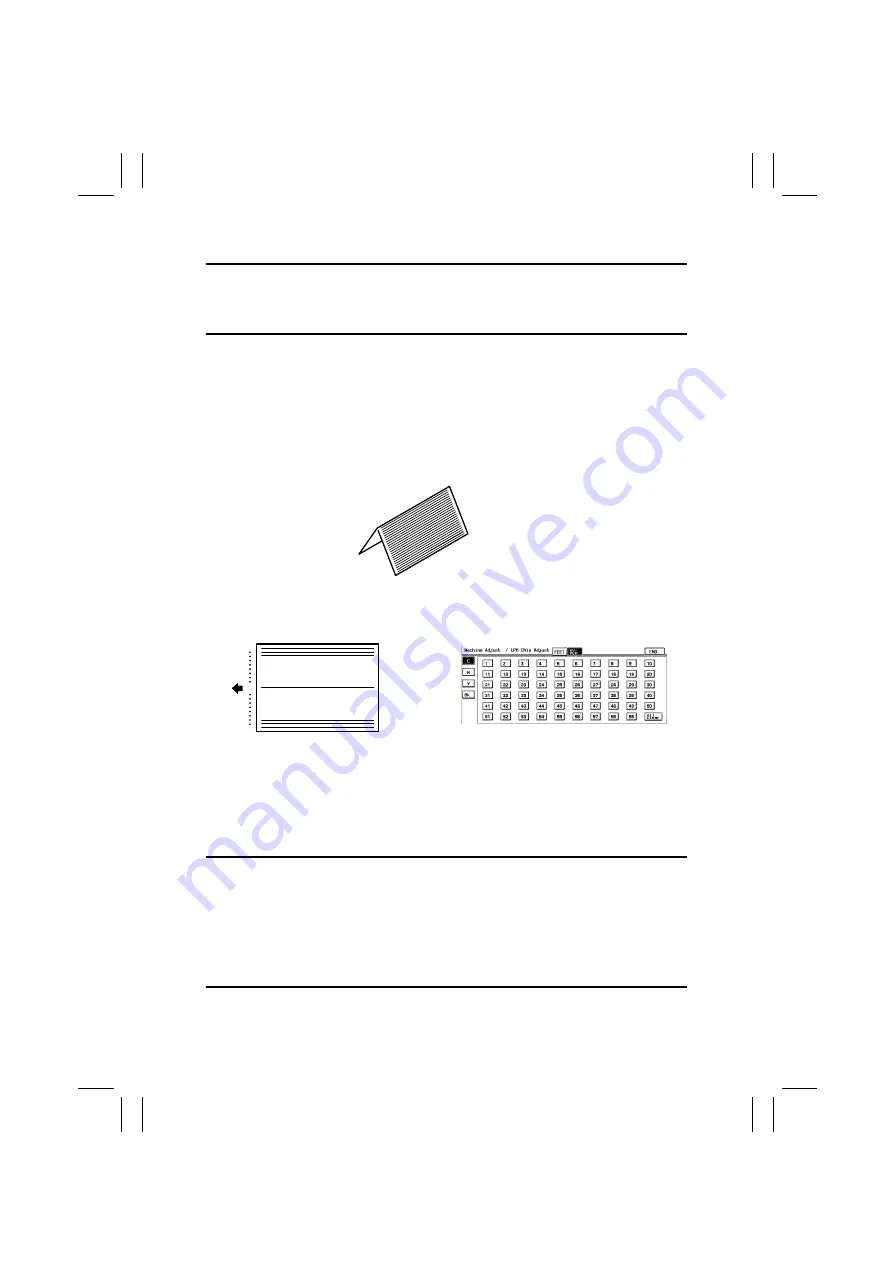
7. Fold the test pattern in half (with the pattern face on the outside).
8. The chip boundary line on the crease (the center) of the test pattern corresponds to the
“30” on the panel. Starting here count out to each side of the paper to identify each
location.
9. Find the number on the panel, to which the location of white lines or black lines in FD
checked in step 5 corresponds.
10. Select the color (C, M, Y, or Bk) in which white lines or black lines in FD occur.
If the lines occur only in green on the test pattern, select Y.
11. Touch the corresponding number on the panel. (It is then highlighted and the setting
value is displayed besides the highlighted number.)
12. Change the setting value using the 10-Key Pad.
Black lines in FD: Decrease the setting value.
White lines in FD: Increase the setting value.
When a new LPH Unit has been installed, corrections can be made for up to eight loca-
tions.
Corrections for up to five locations can be made through factory adjustments. If white
lines or black lines in FD occur, therefore, corrections can therefore be made in the field
for three to eight locations.
If lines persist even after the correction procedures, change the LPH Unit.
13. Select HYPER and color.
14. Press the Start key to let the copier produce a test pattern and check for lines.
4025D127AA
59
30
1
4025D128AB
4025D503CA
Summary of Contents for CF2002
Page 1: ...The essentials of imaging www minoltaeurope com Service Manual CF2002 CF3102 ...
Page 2: ......
Page 21: ...FrameMaker Ver 5 5E PC CF2002 CF3102 GENERAL 02 06 26 GENERAL 14413 ...
Page 30: ...FrameMaker Ver 5 5E PC CF2002 CF3102 MAINTENANCE 02 06 26 MAINTENANCE 14413 ...
Page 178: ...FrameMaker Ver 5 5E PC CF2002 CF3102 TROUBLESHOOTING 02 06 26 TROUBLESHOOTING 14413 ...


