Page 34
Instruction Manual Software
thicknessCONTROL MTS 8201.LLT / 4350006.71
The tabs on the right side can be collapsed by clicking unless this has happened before.
Width can be customized by pulling the separator or by touch-gestures. This can also be
done in the menu bar. This width definition is specific for each tab and can be minimized
and opened again by means of the arrow buttons below. You can also switch between
the tabs using the mouse wheel when the mouse is located above this icons.
5.4
View System Overview
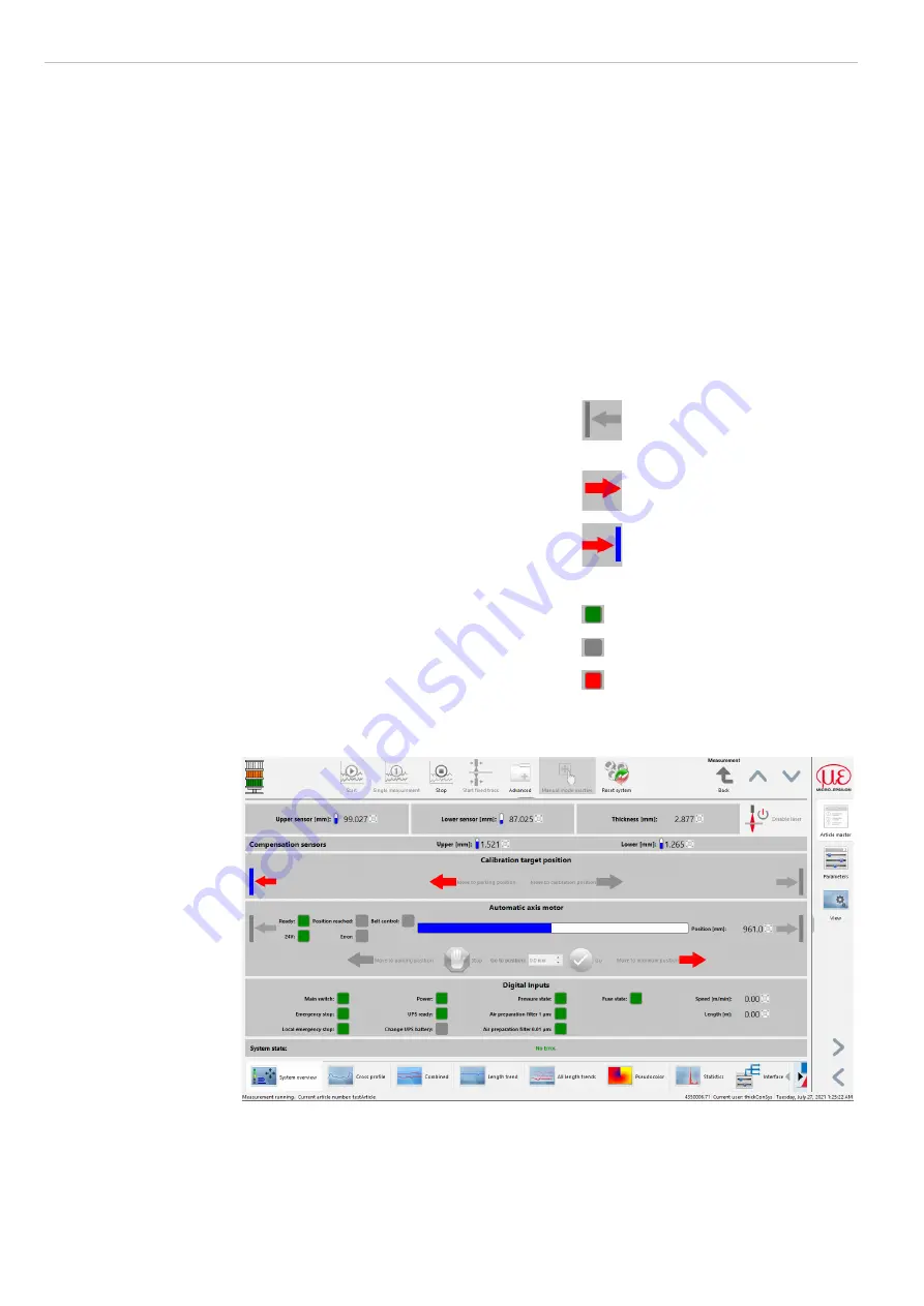
Directly beneath the menu the current measurement values, data and information of the
measuring system are displayed. In view
System overview
, selectable via view tab,
additional information of the measuring system is displayed.
The segment
Calibration target position
shows the current state of the
calibration target. In manual mode the calibration target can be swiveled in/out in the
calibration gap through the
Move to parking position
and
Move to calibra-
tion position
buttons.
In segment
Automatic axis motor
the
same kind of display applies to the limit
switches. Additionally, the horizontal bar view
describes the current position of the automatic
axis. The manual commands are activated and
deactivated via the menu
Measurement >
Manual mode
. The displays of the digital in-
puts show the current state of the servomotor.
Examples symbols, automatic mode
Measurement carriage not in
horizontal motor zero position.
Measurement carriage trav-
erses in maximal position
direction.
Measurement carriage in hori-
zontal parking position.
The segment
Digital inputs
shows the
state of the measuring system by means of
virtual LEDs. E.g. area stop, main switch, USV,
compressed air, safety mechanisms ASO are
surveilled. Additionally, the current speed and
length
are displayed.
Example symbols
Process OK
Process ordinary
Process critical
In the array
Status
the current system errors are displayed in words. These system er-
rors are saved in the window of the system logger.
Fig. 36 System overview
5.4.1
Move
Measurement Carriage, Calibration Target
The actuators of the system can be moved via the corresponding buttons in the view
System overview
if the measurement has not been started and the necessary rights
exist. You can activate resp. deactivate these buttons via the menu
Measurement
>
Manual mode
.
Summary of Contents for 4350006.71
Page 12: ...Page 12 Laser Safety thicknessCONTROL MTS 8201 LLT 4350006 71 ...
Page 62: ...Page 62 Instruction Manual Software thicknessCONTROL MTS 8201 LLT 4350006 71 ...
Page 64: ...Page 64 Pneumatic Plan thicknessCONTROL MTS 8201 LLT 4350006 71 ...
Page 70: ...Page 70 Declaration of Incorporation thicknessCONTROL MTS 8201 LLT 4350006 71 ...
Page 95: ...Operating Instructions scanCONTROL 29xx ...
Page 100: ......
Page 135: ...Page 41 Operation of the Sensor with a PC scanCONTROL 29xx Fig 24 Predefined measuring fields ...
Page 193: ......
Page 194: ......
Page 229: ......


