MI 3290 Earth Analyser
Tests and Measurements
85
Refer to
for more information on sub-procedure of
the Selective Flex method.
Test can be started from the Selective (Flex Clamps 1-4) measurement window. Before
carrying out a test the following parameters (Test Mode, Test Frequency, Number of turns F1
- F4, Distance and Limit (Z
tot
) can be edited.
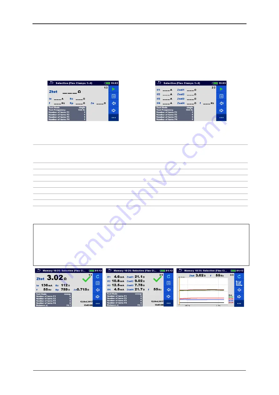
Figure 11.32: Selective (Flex Clamps 1-4) measurement menu
Test parameters for Selective (Flex Clamps 1-4):
Test Mode
Set test mode: [single, sweep].
Test Frequency*
Set test frequency: [55 Hz, 82 Hz, 94 Hz, 105 Hz, 111 Hz, 128 Hz,
164 Hz, 329 Hz, 659 Hz, 1.31 kHz, 1.50 kHz, 2.63 kHz, 3.29 kHz,
6.59 kHz]
Number of turns F1
Set the number of turns for Flex 1 input terminal: [1, 2, 3, 4, 5, 6]
Number of turns F2
Set the number of turns for Flex 2 input terminal: [1, 2, 3, 4, 5, 6]
Number of turns F3
Set the number of turns for Flex 3 input terminal: [1, 2, 3, 4, 5, 6]
Number of turns F4
Set the number of turns for Flex 4 input terminal: [1, 2, 3, 4, 5, 6]
Distance (r)
Distance between E and S probe (user defined).
Distance (R)
Distance between E and auxiliary earth rod H (user defined).
Limit (Ztot)
Limit value selection: [
OFF, 0.1 Ω – 5.00 kΩ]
*single test mode only.
Selective (Flex Clamps 1-4) Measurement procedure:
Select the
Selective (Flex Clamps 1-4) measurement function.
Set the test parameters (mode, frequency, number of turns and limit).
Connect the test leads and flex clamps to the instrument and to the test object.
Press the Run key to start the measurement.
Wait until the test result is displayed on the screen.
Press the cursor keys to toggle between graph view and multiple result views.
Save results (optional).
Figure 11.33: Example of
Selective (Flex Clamps 1-4)
measurement result - Z
tot
Figure 11.34: Example of
Selective Flex Clamps 1-4)
measurement result
– Z
sel1-4
Figure 11.35: Example of
Selective Flex Clamps 1-4)
measurement graph view


